Трябва да сте влезли в
Category
Интересувате ли се от този продукт? Имате ли нужда от допълнителна информация или индивидуални цени?
Трябва да сте влезли
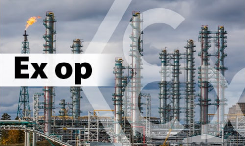 Promieniowanie optyczne - jak się przed nim chronić?
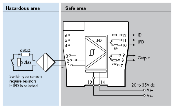
 Искробезопасност - Основни насоки