Vous devez être connecté
Category
Êtes-vous intéressé par ce produit? Avez-vous besoin d'informations supplémentaires ou d'une tarification individuelle?
Vous devez être connecté
 Promieniowanie optyczne - jak się przed nim chronić?
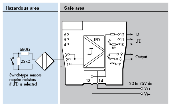
 Sécurité intrinsèque - Directives de base