Technical data
| Voltage Supply |
24V AC/DC -15%/+10%
Not polarity sensitive |
| Detector type |
Optical UG-5-AFR-24V |
| Max. power consumption |
220mA |
| Operating temperature |
-10°C…+55°C |
| Maximum humidity |
99%rh |
| Duct air velocity range |
1…20 m/s |
| Approvals |
VdS CE, EN-54-27 |
| Relay output |
Potential free |
| Smoke alarm relays |
Two changing contacts 250V, 8A |
| Service alarm |
One breaking contact 250V, 5A |
| System error alarm |
One breaking contact 250V, 5A |
| Low Flow alarm |
One breaking contact 250V, 5A |
| LED on smoke detector |
Green - service alarm (contamination)
Red - smoke alarm |
| LED on PCB |
Green - normal operation
Yellow - system error
Yellow - Low-Flow |
| Adaptor housing |
ABS |
| Protection class |
IP54 |
| Air sampling tube |
Aluminium |
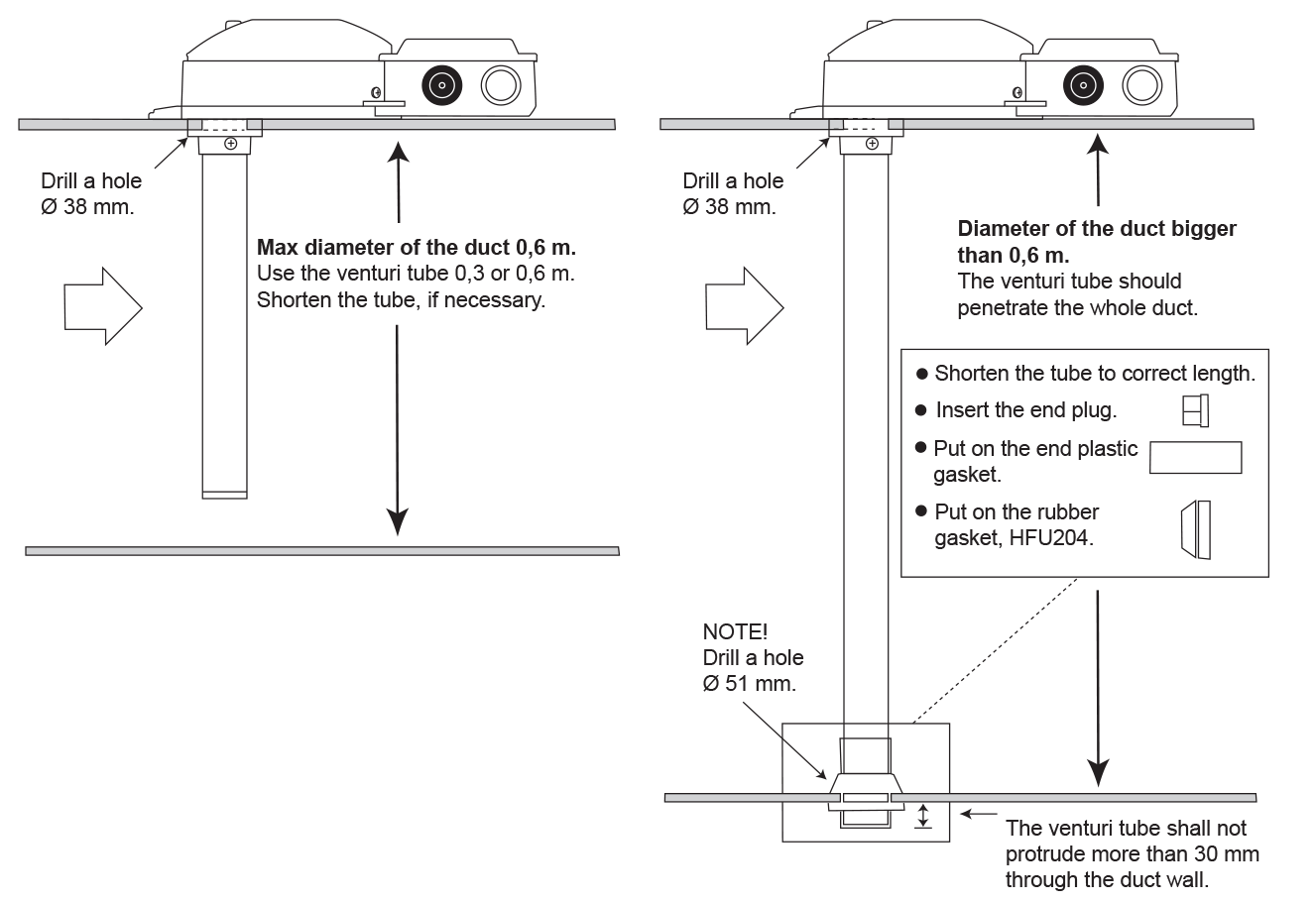
Standard length 0,6 m. Hole diameter 38 mm. The length of the venturi pipe shall be chosen based upon how wide the ventilation duct is. The venturi pipes are available in 4 lengths; 0,3 m, 0,6 m, 1,5 m and 2,8 m. When the ventilation duct is wider than 0,6 m (dia), the venturi pipe should penetrate the whole duct. Please see below sketch.
Characteristics
- Automatic sensitivity adjustment enables longer lifespan and fewer false alarms due to contamination
- Patented venturi pipe
- One-pipe air sampling system Uniguard Superflow
- Service alarm
- Test hole on cover
- Simple installation
- Electronic air-flow indicator
Function
Uniguard has been developed to detect smoke in ventilation ducts and combines a smoke detector and an adaptor system where both tube and housing are specially designed for optimum airflow through the smoke detector. The UG-5 can be installed on any side of the duct in four different positions: 0°, 90°, 180° and 270°. Patented.
Relays
- Two alarm relays to control fire-safety dampers, to stop ventilation fans or to activate acoustic and optical alarms etc.
- One service alarm relay to let you know when maintenance is needed, before a false alarm occurs.
- One system error relay indicating fault on the smoke detector circuit.
- One Low-Flow relay indicating that air flow in the duct is low or that the UG-5 is installed in an inexpedient place on the duct.
Any receiving device of relay status should consider alarm indications up to 10 milliseconds as normal no-alarm condition. Receiving devices can be: Actuator for fire/smoke dampers, fire alarm panels, smoke evacuation fans etc. The detector contains an intelligent controlling circuit. This circuit is adjusting the sensitivity to give an optimal function during the whole life time of the detector. When the controlling circuit has reached the maximum sensitivity compensation for contamination, a service alarm is indicated. The detector has a bayonet fitting to simplify mounting and removal.
Basic principles for positioning
For the airflow through the adaptor to be representative of the airflow in the ventilation duct, install the detector at a place where flow meters etc. normally are mounted, please see our installation instructions. You can also use your national or local rules for mountage according to "Methods for measuring airflow in ventilation systems".
Installation
The venturi pipe is made of aluminium and can easily be shortened to suit the diameter of the duct. Hole diameter is 38 mm. For insulated or small circular ducts (100-150 mm) - use the mounting bracket, hole diameter is then 51 mm.
Maintenance
The detector contains an intelligent controlling circuit. This circuit is adjusting the sensitivity to give an optimal function during the whole life time of the detector. When the controlling circuit has reached the maximum sensitivity compensation for contamination, a service alarm is indicated. This can be postponed for a considerable time by cleaning the detector once a year with a vacuum cleaner.
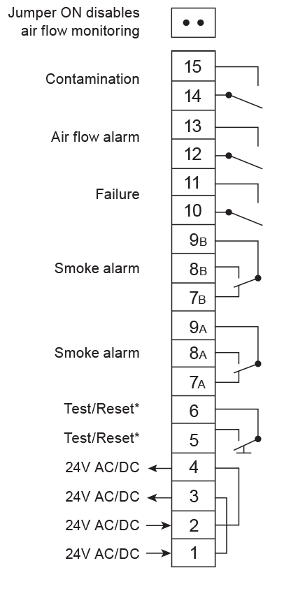
Air flow monitoring
The detector has an electronic air flow monitoring. When the detector is correctly installed, the yellow “Low-Flow” LED is turned out. The function provides a simple confirmation that the air flow from the duct is in fact flowing through the housing. It is possible to disable the air flow monitoring in case of special installations.
Function test
When the installation is complete, the detector should be tested. This can be carried out with smoke or suitable testspray, for example RDP-300 (from Calectro). Use the test hole on the cover. Do not forget to refit the plastic plug after test.
NB: When installing outdoors or in cold attics etc, where there is a risk for condensation, the detector should be insulated from the surrounding air with e.g. our weatherproof housing UG-COVER-75. In such cases it should be marked with a sign "Hidden Detector".
Function
| Normal operation |
: In normal operation all relays are energized. |
| Smoke alarm |
The LED of the detector is showing red light. |
| Reset |
Press the reset button to reset the detector into normal operation. |
| Service alarm |
When the detector is sensing smoke or is dirty the LED of the detector will first show green colour before going into alarm with red light. If the detector is dirty, it will show green light. This is an optical indication (a pre-alarm or servicealarm) which means that the detector is contaminated and if it is not cleaned, it will give a false alarm later on. |
| Failure |
If an error on the internal smoke detector circuit occurs or when the smoke detector is removed, the yellow system error LED is lit and smoke alarm, service alarm and system error alarm relays are deenergized. |
| Low air flow |
The yellow Low-Flow LED is lit (and the relay is de-energized), when the air speed in the duct is low or if the UG-5 is installed in an inexpedient position on the duct or if the UG-5 is very dirty. To make sure that the smoke detection function is working, apply smoke (i.e. from a smoke machine) into the duct to check that the UG-5 is indicating a smoke alarm. |
Wiring diagram
The relay outputs are shown in power off/alarm condition.
Ordering example
UG-5-AFR-24V - Optical duct smoke detector, stand alone
Accessories
- UG-COVER-75 Waterproof housing (for mounting outdoors, in cold attics etc.)
- ST2 Venturi tube 0,6m
- ST5 Venturi tube 1,5m
- ST9 Venturi tube 2,8m


