ПотврдаИП44 / зависно од монтаже и положаја према ЕН 60034-5
Излазна функцијаАналогни излази 0/4-20 мА, 0-10 В, излази/релеји
Измерена вредностЕлектронска заштита од блокираног ротора.
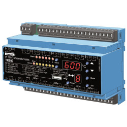
<п>Пт 100 термостат ТР600 је регулатор температуре и надгледа до шест Пт 100 сензора истовремено. Шест уклопних тачака и шест релеја дозвољавају скоро сваку комбинацију прекидача. Такође може изабрати највишу температуру групе од три или шест сензора. Температуре два сензора или групе сензора могу се издати на 2 аналогна излаза, односно за даљинске дисплеје или даљу евалуацију. Програмирање је веома променљиво и једноставно.<п>Због чињенице да се може повезати 6 сензора типа Пт 100, јединица је посебно погодна за праћење температуре где год се истовремено мора надгледати до 6 различитих мерних тачака:<ул><ли>мотори и генератори уз истовремени надзор лежајева и трансформатора са додатним надзором температуре расхладне течности.<ли>мотора и генератора. такође.<ли>енергетске машине и постројења<п>Одобрење<бр />УЛ Е377414 Опрема за управљање процесима, електрична - компонента<п>Преглед функција<ул><ли>Опсег мерења и надзора -199 ... +800 °Ц<ли>2- или 2-лински релејни излаз са 2- или 3-7 улаза са сензором преклопни контакт<ли>Аларм 1 … 6 релеј К1 (12.11.14.) ... К6 (61/62/64)<ли>Релеј грешке сензора К7 (71/72/74) прати прекид сензора или кратак спој сензора.<ли>2 аналогна излаза, 0/4...0 м, 0 В 20/20/2. скалирање.<ли>Универзално напајање. 2 опсега АЦ/ДЦ 24-60В или АЦ/ДЦ 90-240 В<ли>Универзално напајање АЦ/ДЦ 24-240 В<ли>Терминал за УСБ-стицк за подизање и преузимање скупова параметара и ажурирања фирмвера<ли>Оквир за инсталацију за таблу за инсталацију ЕР8 монтирање<ли>Алтернатива: тип релеја за температуру ТР660ИП
ПотврдаИП44 / зависно од монтаже и положаја према ЕН 60034-5
Излазна функцијаАналогни излази 0/4-20 мА, 0-10 В, излази/релеји
Измерена вредностЕлектронска заштита од блокираног ротора.
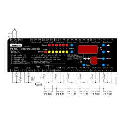
<п>Пт 100 термостат ТР600 је регулатор температуре и надгледа до шест Пт 100 сензора истовремено. Шест уклопних тачака и шест релеја дозвољавају скоро сваку комбинацију прекидача. Такође може изабрати највишу температуру групе од три или шест сензора. Температуре два сензора или групе сензора могу се издати на 2 аналогна излаза, односно за даљинске дисплеје или даљу евалуацију. Програмирање је веома променљиво и једноставно.<п>Због чињенице да се може повезати 6 сензора типа Пт 100, јединица је посебно погодна за праћење температуре где год се истовремено мора надгледати до 6 различитих мерних тачака:<ул><ли>мотори и генератори уз истовремени надзор лежајева и трансформатора са додатним надзором температуре расхладне течности.<ли>мотора и генератора. такође.<ли>енергетске машине и постројења<п>Одобрење<бр />УЛ Е377414 Опрема за управљање процесима, електрична - компонента<п>Преглед функција<ул><ли>Опсег мерења и надзора -199 ... +800 °Ц<ли>2- или 2-лински релејни излаз са 2- или 3-7 улаза са сензором преклопни контакт<ли>Аларм 1 … 6 релеј К1 (12.11.14.) ... К6 (61/62/64)<ли>Релеј грешке сензора К7 (71/72/74) прати прекид сензора или кратак спој сензора.<ли>2 аналогна излаза, 0/4...0 м, 0 В 20/20/2. скалирање.<ли>Универзално напајање. 2 опсега АЦ/ДЦ 24-60В или АЦ/ДЦ 90-240 В<ли>Универзално напајање АЦ/ДЦ 24-240 В<ли>Терминал за УСБ-стицк за подизање и преузимање скупова параметара и ажурирања фирмвера<ли>Оквир за инсталацију за таблу за инсталацију ЕР8 монтирање<ли>Алтернатива: тип релеја за температуру ТР660ИП