Musisz być zalogowany/a
Category
Jesteś zainteresowany tym produktem? Potrzebujesz dodatkowych informacji lub indywidualnej wyceny?
Musisz być zalogowany/a
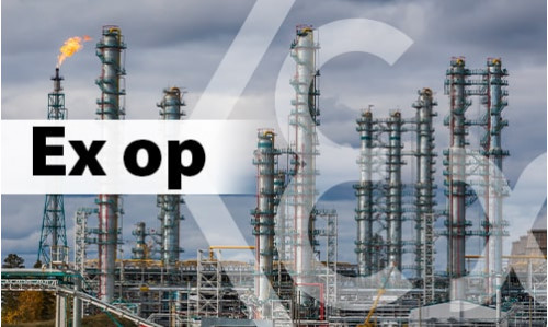
 Горючість зерна – які фактори впливають на займистість?
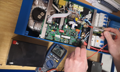
 Оптичне випромінювання – як від нього захиститися?
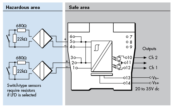
 Іскробезпека - Основні рекомендації