Base device for single-channel or two-channel emergency stop and safety gate applications with access delay
• Stop category 0 according to EN 60204-1
• Applications up to safety category 4/3 according to EN 954-1
• Safety category of the device: 4 (undelayed contacts) /
3 (delayed contacts) according to EN 954-1
• OFF-delay time adjustable in the range 0.15 to 3 s or 1.5 to 30 s
• Control through contacts or semiconductors
• Reset button monitoring, cross monitoring, synchrocheck
• 3 enabling current paths (2 undelayed, 1 ON-delayed)
Application
• Protection of people and machinery
• Monitoring of interlocking installation with position switches and integrated locking
• ON-delay unlocking of the solenoid integrated in the position switches
Function
Device and function description
With supply voltage applied to terminals A1 /A2, the relays K3and K4 (terminals 37 / 38)start with the pre-selected ON-delay time. The ON-delay time tA1 can be adjusted infinitely in the range 0.15 to 3 s or 1.5 to 30 s according to the device type. The deviceis enabled by pressing the reset button. The following operating modes can be selected: Operating mode with reset button monitoring(evaluation of the falling edge; manual start)
The reset button must be connected to S34 through terminal S33. For starting the relay the reset button must be pressed. Relays K3 and K4 (terminals 37 / 38) will switch into the OFF position. With the falling edge of the reset signal the reset is completed and activates the relays K1 and K2, which become self-locking after the response time t=A3. After this switch-on phase the 2 enabling current paths defined for the output are closed (terminals 13 / 14, 23 / 24). With the emergency stop command the power supply to relays K1 and K2 is interrupted. The enabling current paths (terminals 13 / 14, 23 / 24) are immediately opened with release time tR, and the relays K3 and K4 will start afterthe pre-set ON-delay time tA1, terminals 37 / 38. Three LEDs display the state of the relays K1/ K2, K3 / K4 and the supply voltage.
Operating mode without reset button monitoring
(evaluation of the rising edge; automatic start)
For monitoring of interlocking installations with locking mechanism or safety gate applications in which an automatic start shall be performed it is necessary to jumper terminals S33 / S35. The device will react at the rising edge of input S12 that is internally connected to S33. Relays K3 and K4 (terminals 37 / 38) will switch into the OFF position. With the rising edge of input S12 the relay K1 is activated and response time tA2 started. When the time has elapsed, the 2 enabling current paths are closed (terminals 13 / 14, 23 / 24). With a stop command the power supply to relays K1 and K2 is interrupted. The enabling current paths (terminals 13 / 14, 23/24) are immediately opened with release time tR, and the relays K3 and K4 will start after the pre-set ON-
delay time tA1, terminals 377/38. With a two-channel control and cross-monitoring wiring of the sensor circuit, additional errors such as shunt fault or ground fault can be detected. An electronic fuse protects the device against damage. After the cause of the malfunction has been removed, the device is operational again after approx. 3 s.
Synchrocheck
The use of safety limit switches for single-channel or two-channel circuits in safety gate applications depends on the required safety level. The device offers a two-channel control along with an optional synchrocheck of the limit switches.A synchronous time ts=0.5 s requires limit switches positioned in a way that channel 1, terminals S11/ S12, closes before channel 2, terminals S21/ S22 or S11/31. If channel 2 closes before channel 1, the synchronous time is ts=∞
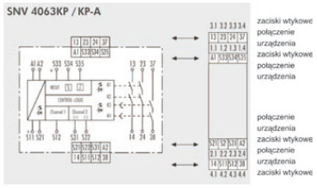
Connection scheme
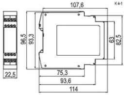
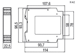
Dimensions [mm]
SNV 4063KP
SNV 4063KP-A
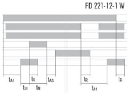
Function diagram
|
Emergency stop application (installation 2 and 3)
|
 |
A1/ A2, supply voltage, LED SUPPLY
S12 emergency stop channel 1
S31/ S22 emergency stop channel 2
S34 reset; falling edge
13/14, 23/24, LED K1/K2
37/38, LED K3/K4
tA1 = ON-delay time (selectable
tA3 = response time
tM = minimum ON time
tR = release time
tW = recovery time
|
| |
|
Safety gate application (installation 1
|
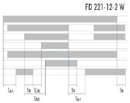 |
A1/ A2, supply voltage, LED SUPPLY
Stop S21/S22, S11/S12
S12 channel 1 SK
S31/ S22 channel 2 UK
S35 reset; rising edge
13/14, 23/24, LED K1/K2
37/38, LED K3/K4
tA1 = ON-delay time (selectable)
tA2 = response time; between closing of the gate and disable
tR = release time
tOK = time necessary for the monitoring contact to lock |
Proper use
The devices are safety switching devices. They must only be used as components of
safety equipment on machines for the purpose of protecting people, material and
machines.
• The safety category according to EN 954-1 depends on the external circuitry, the
choice of control devices and their placement on the machine.
• The reset button used for manual start (S34) must not be actuated for more than 3 s.
The indicated times must be observed when the device is operated, otherwise the
device could lock. Locking can be released by properly opening the safety inputs.
• SNE expansion devices or external contactors with positively driven contacts can be
used to multiply the enabling current paths.
• The device and the contacts must be protected with max. 6 A utilization category gG
or through circuit breakers with trigger characteristic B or C.
• The devices are equipped with overload protection (for short circuit). After the cause
of the malfunction has been removed, the device is operational again after approx. 3 s.
• Control output S11/S33 is exclusively for connecting control devices as defined in the
operating instructions and not for connecting external field devices such as lamps,
relays or contactors.
• The emergency stop circuit must be closed before the reset button is activated.
• For connecting sensors with reed contacts or semiconductor outputs the inrush current
must be considered (see “Technical data”).
• The devices must be installed in a control cabinet with a protection degree of at least
IP 54
| Description/number |
| type |
Turn off delay |
Nominal voltage |
Terminals |
number Std. pack |
| SNV 4063KP |
3 s |
DC 24V |
screw terminals |
R1.188.0650.0 1 |
| 30 s |
DC 24V |
screw terminals |
R1.188.0670.0 1 |
| SNV 4063KP-A |
3 s |
DC 24V |
screw plug terminals |
R1.188.0660.0 1 |
| 30 s |
DC 24V |
screw plug terminals |
R1.188.0680.0 1 |
| Technical data |
SNV 4063KP |
|
Function
|
Emergency stop relay for access delay combined with locking mechanism
|
|
|
3 LED, green
|
Function mode / adjustment
|
FD 221-12-1 W, FD 221-12-2 W
|
|
|
min
|
type
|
max
|
|
Rated voltage Un
|
DC 20,4 V
|
DC 24 V
|
DC 26,4 V
|
|
Rated consumption DC
|
|
1,8 W
|
|
|
Control circuit
|
|
|
Rated output voltage S11/S33
|
|
DC 22 V
|
|
|
for S34, S35, S12, S31, S22
|
|
|
Input current / peak current S12, S31, S22
|
|
25 mA/100 mA
|
|
|
Input current / peak current S34, S35
|
|
40 mA/50 mA
|
|
|
Response time tA1
|
0,15 s ±16%
1,5 s ±16%
|
30 ms
|
3 s ±16%
30 s ±16%
|
|
Response time tA2/ tA3
|
|
700 ms/30 ms
|
|
|
Release time tR
|
|
40 ms
|
|
|
Minimum ON time tM S33-S34
|
200 ms
|
|
|
|
Minimum ON time tM S33-S35
|
200 ms
|
|
∞
|
|
Recovery time tW (Start)
|
|
|
500 ms
|
|
Synchronous time tS
|
100 ms
|
|
500 ms
|
|
|
|
|
Enabling paths
|
normally open contact
normally open contact, ON-delayed
forcebly guided
|
|
Rated switching voltage Un
|
AC/DC 230 V
|
|
Max. thermal current
|
6 A
|
|
Max total current
|
12 A
|
|
Application category EN 60947-5-1
|
AC-15: Ue 230 V AC, Ie 4 A (3600 cycles/h)
DC-13: Ue 24 V DC, Ie 5 A (360 cycles/h)
|
|
Short-circuit protection (NO), lead fuse / circuit breaker
|
6 A Class gG / melting integral < 100 A²s
|
|
|
|
|
Creepage distances and clearances between the circuits
|
EN 60664-1
|
|
Rated voltage shock resistance
|
4 kV
|
|
Overvoltage category
|
III
|
|
Measuring voltage
|
AC 300 V
|
| Protection degree according to DIN EN 60529 (housing / terminals) |
IP 40/IP 20
|
|
Ambient temperature / storage temperature
|
-25 - +55 °C/-25 - +75 °C
|
| Drawing |
K 4-1 (screw terminals/K 4-2 (plug terminals)
|
|
Wire ranges screw terminals, fine-fine-stranded with ferrules stranded / solid
|
2x0,14 - 0,75 mm2/1x0,14 - 2,5 mm2
1x0,25 - 2,5 mm2/2x0,25 - 0,5 mm2
|
|
|
0,5 - 0,6 Nm
|
|
Weight
|
0,2kg
|
|
Accessories
|
-
|


