
Jūs turite būti prisijungę
Category


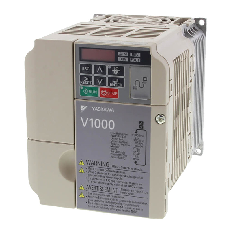
Nuotraukos yra skirtos tik informaciniams tikslams. Peržiūrėkite produkto specifikaciją
please use latin characters
| V | V1000 series |
| Z |
Z: European standard
specifications |
| A |
A: Standard specs
|
| B |
Voltage:
B: Single-phase 200 VAC 2: Three-phase 200 VAC 4: Three-phase 400 VAC |
| O P 1 |
[”P” indicates a decimal point]
Max. applicable motor output 0P1: 0.1 kW ~ 015: 15 kW |
| B |
Enclosure, Fin, Filter:
B: IP20 without top cover F: Nema 1 E: IP20 without top cover and C3 filter |
| A |
Coating specs:
A: Standard |
| A | Version |
| Single-phase:: VZ-@ | B0P1 | B0P2 | B0P4 | B0P7 | B1P5 | B2P2 | B4P0 | - | - | - | - | |
|---|---|---|---|---|---|---|---|---|---|---|---|---|
| Three-phase: VZ-@ | 20P1 | 20P2 | 20P4 | 20P7 | 21P5 | 22P2 | 24P0 | 25P5 | 27P5 | 2011 | 2015 | |
| Motor [ kW]1 | For HD setting | 0,12 | 0,25 | 0,4 | 0,75 | 1,5 | 2,2 | 4,0 | 5,5 | 7,5 | 11 | 15 |
| For ND setting | 0,18 | 0,37 | 0,75 | 1,1 | 2,2 | 3,0 | 5,5 | 7,5 | 11 | 15 | 18,5 | |
| Output characteristics |
Inverter capacity kVA | 0,3 | 0,6 | 1,1 | 1,9 | 3,0 | 4,2 | 6,7 | 9,5 | 13 | 18 | 23 |
| Rated output current (A) at HD | 0,8 | 1,6 | 3,0 | 5,0 | 8,0 | 11,0 | 17,5 | 25,0 | 33,0 | 47,0 | 60,0 | |
| Rated output current (A) at ND | 1,2 | 1,9 | 3,5 | 6,0 | 9,6 | 12,0 | 21,0 | 30,0 | 40,0 | 56,0 | 69,0 | |
| Max. output voltage | Proportional to input voltage: 0..240 V | |||||||||||
| Max. output frequency | 400 Hz | |||||||||||
| Power supply |
Rated input voltage and frequency |
Single-phase 200..240 V 50/60 Hz 3-phase 200..240 V 50/60 Hz |
||||||||||
| Allowable voltage fluctuation |
-15% - +10% | |||||||||||
| Allowable frequency fluctuation |
+5% | |||||||||||
1) Based on a standard 4-pole motor for maximum applicable motor output:
Heavy Duty (HD) mode with a 150% overload capacity
Normal Duty (ND) mode with a 120% overlaod capacity
| Three-phase: VZ-@ | 40P2 | 40P4 | 40P7 | 41P5 | 42P2 | 43PO | 44P0 | 45P5 | 47P5 | 4011 | 4015 | |
|---|---|---|---|---|---|---|---|---|---|---|---|---|
| Motor [ kW]1 | For HD setting | 0,2 | 0,4 | 0,75 | 1,5 | 2,2 | 3,0 | 4,0 | 5,5 | 7,5 | 11 | 15 |
| For ND setting | 0,37 | 0,75 | 1,5 | 2,2 | 3,0 | 3,7 | 5,5 | 7,5 | 11 | 15 | 18,5 | |
| Output characteristics |
Inverter capacity [kVA] | 0,9 | 1,4 | 2,6 | 3,7 | 4,2 | 5,5 | 7,2 | 9,2 | 14,8 | 18 | 24 |
| Rated output current (A) at HD | 1,2 | 1,8 | 3,4 | 4,8 | 5,5 | 7,2 | 9,2 | 14,8 | 18 | 24 | 31 | |
| Rated output current (A) at ND | 1,2 | 2,1 | 4,1 | 5,4 | 6,9 | 8,8 | 11,1 | 17,5 | 23 | 31 | 38 | |
| Max. output voltage | 0..480V (proportional to input voltage) | |||||||||||
| Max. output frequency | 400 Hz | |||||||||||
| Power supply |
Rated input voltage and frequency |
3-phase 380..480 VAC, 50/60 Hz | ||||||||||
| Allowable voltage fluctuation |
-15% do +10% | |||||||||||
| Allowable frequency fluctuation |
+5% | |||||||||||
| Model number VZ-D | Specifications | |
|---|---|---|
| Control functions | Control methods Sine wave PWM (V/f control, sensorless current vector control) | |
| Output frequency range | 0,1-400 Hz | |
| Frequency tolerance | Digital set value: ±0.01% (-10..+50 ºC) | |
| Analogue set value: ±0.1% (25 ±10 ºC) | ||
| Resolution of frequency set value | Digital set value: 0.01 Hz (<100 Hz), 0.1 Hz (>100 Hz) | |
| Analogue set value: 1/1000 of maximum frequency | ||
| Resolution of output frequency 0.01 Hz | 0,01 Hz | |
| Overload capability | Heavy duty use: 150% rated output current for one minute Normal duty use: 120% rated output current for one minute |
|
| Frequency set value | 0..10 V (20 kΩ), 4..20 mA (250 Ω), 0..20 mA (250 Ω) Pulse train input, frequency setting value (selectable) |
|
| Braking torque (short term peak torque) |
Short-term average deceleration torque: 150% (up 1.5 kW), 100% (for 1.5 kW), 50% (for 2.2 kW), 20% (fof bigger size) Continous regenerative torque: Aprox 20% (125% with optional braking resistor, 10%ED, 10 s, braking transistor built itn) |
|
| V/f Characteristics | Possible to program any V/f pattern | |
| Inputs signals | Seven of the following input signals are selectable: Forward/reverse run (3-wire sequence), fault reset, external fault (NO/NC contact input), multi-step speed operation, Jog command, accel/decel time select, external baseblock, speed search command, UP/DOWN command, accel/decel hold command, LOCAL/REMOTE selection, communication/control circuit terminal selection, mergency stop fault, emergency stop alarm, self test |
|
| Output signals | Following output signals are selectable (NO/NC contact output, 2 photo-coupler outputs): Fault, running, zero speed, speed agree, frequency detection (output frequency <= or => set value), during overtorque detection, minor error, during baseblock, operation mode, inverter run ready, during fault retry, during undervoltage detection, reverse running, during speed search, data output through communication. |
|
| Standard functions | Open-loop vector control, full-range automatic torque boost, slip compensation, 17-step speed operation (max.), restart after momentary power loss, DC injection braking current at stop/start (50% of inverter rated current, 0.5 sec, or less), frequency reference bias/gain, MEMOBUS communications (RS-485/422, max. 115K bps), fault retry, speed search, frequency upper/ lower limit setting, overtorque detection, frequency jump, accel/decel time switch, accel/decel prohibited, S-curve accel/decel, PID control, energy-saving control, constant copy. |
|
| Analogue inputs | 2 analogue inputs, 0..10 V, 4..20 mA, 0..20 mA | |
| Braking/acceleration times 0.01..6000 s | ||
| Display | Optionally frequency, current or set value | |
| Error and status LED | ||
| Motor overload protection Electronic thermal overload relay | ||
| Instantaneous overcurrent | Motor coasts to a stop if DC bus voltage exceed 410 V (double for 400 V class) | |
| Overload | Heavy Duty: Motor coasts to a stop after 1 minute at 150% of inverter rated output current Normal Duty: Motor coasts to a stop after 1 minute at 120% of inverter rated output current |
|
| Overvoltage | Motor coasts to a stop if DC bus voltage exceed 410 V (double for 400 V class) | |
| Undervoltage | Stops when DC bus voltage is approx. 190 V or less (double for 400 V class) (approx. 150 V or less for single-phase series) |
|
| Momentary power loss | Following items are selectable: not provided (stop if power loss is 15 ms or longer), continuous operation if power loss is approx. 0.5 s or shorter, continuous operation |
|
| Cooling fin overheat | Protected by thermister | |
| Stall prevention level | Stall prevention level Stall prevention during acceleration/deceleration and constant speed operation | |
| Ground fault | Protected by electronic circuit (operation level is approx. 250% of rated output current) | |
| Power charge indication | Indicates until the main circuit voltage reaches 50 V. | |
| Degree of protection | IP20, NEMA1 | |
| Cooling | Cooling fan is provided for 200 V, 0.75 kW (1HP) (3/single-phase) 400 V, 1.5 kW (2HP) (3-phase), others are self-cooling |
|
| Ambient humidity | 95% RH or less (without condensation) | |
| Storage temperature | -20 ºC..+60 ºC (short-term temperature during transportation) | |
| Installation | Indoor (no corrosive gas, dust, etc.) | |
| Installation height Max. 1000 m | Maks. 1000 m | |
| Vibration | Up to 9.8 m/s2 at 10 to less than 20 Hz, Up to 6.37 m/s2 at 20 to 50 Hz | |
|
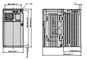
Drawing 1
 |
Drawing 2
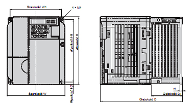 |
| Voltage class | Max. applicable motor output kW [kW] |
Inverter model VZA | Drawing | Dimensions in mm | Masa | |||||||||
|---|---|---|---|---|---|---|---|---|---|---|---|---|---|---|
| W1 | H1 | W | H | D | tl | H2 | D1 | H3 | H4 | |||||
| Single-phase 200 V |
0,12 | B0P1 | 1 | 56 | 118 | 68 | 128 | 76 | 3 | 5 | 6,5 | 0,6 | ||
| 0,25 | B0P2 | 0,7 | ||||||||||||
| 0,55 | B0P4 | 108 | 5 | 38,5 | 1,0 | |||||||||
| 1,1 | B0P7 | 2 | 96 | 108 | 137,5 | 58 | 1,5 | |||||||
| 1 5 | B1P5 | 154 | 1 5 | |||||||||||
| 2,2 | B2P2 | 128 | 140 | 163 | 65 | 2,1 | ||||||||
| 4,0 | B4P0 | W trakcie opracowania | ||||||||||||
| Three-phase 200V |
0,12 | 30P1 | 1 | 56 | 118 | 68 | 128 | 76 | 3 | 5 | 6,5 | - | - | 06 |
| 0,25 | 20P2 | 0,6 | ||||||||||||
| 0,55 | 20P4 | 108 | 5 | 38,5 | 0,9 | |||||||||
| 1 1 | 30P7 | 128 | 1 1 | |||||||||||
| 1,5 | 21P5 | 2 | 96 | 108 | 129 | 58 | 1,3 | |||||||
| 2,2 | 22P2 | 137,5 | 1,4 | |||||||||||
| 40 | 34P0 | 128 | 140 | 143 | 65 | 2,1 | ||||||||
| 5,5 | 25P5 | 3 | 122 | 248 | 140 | 254 | 140 | - | 6 | 55 | 13 | 6,2 | 3,0 | |
| 7,5 | 27P5 | 3,8 | ||||||||||||
| 11 | 9011 | 160 | 284 | 180 | 290 | 163 | 8 | 75 | 15 | 5,5 | ||||
| 15 | 2015 | 192 | 336 | 220 | 358 | 187 | 7 | 78 | ' | 9,2 | ||||
| Three-phase 400V |
0,37 | 40P2 | 2 | 96 | 118 | 108 | 128 | 81 | 5 | 5 | 10 | - | 0,8 | |
| 0,55 | 40P4 | 99 | 78 | 1 0 | ||||||||||
| 1,1 | 40P4 | 137,5 | 58 | 1,4 | ||||||||||
| 1,5 | 41P5 | 154 | 1,5 | |||||||||||
| 3 3 | 43P3 | 1 5 | ||||||||||||
| 3,0 | 43P0 | 1,5 | ||||||||||||
| 4,0 | 44P0 | 128 | 140 | 143 | 65 | 2,1 | ||||||||
| 5,5 | 45P5 | 3 | 122 | 248 | 140 | 254 | 140 | " | 6 | 55 | 13 | 6 | 3,8 | |
| 7,5 | 47P5 | 6,2 | 3,8 | |||||||||||
| 11 | 4011 | 160 | 284 | 180 | 290 | 143 | 8 | 15 | 6 | 5,2 | ||||
| 15 | 4015 | 163 | 75 | 5,5 | ||||||||||
Ar Jūs domina šis produktas? Ar Jums reikia papildomos informacijos ar individualaus pasiūlymo?
tu turi būti prisijungęs
| V | V1000 series |
| Z |
Z: European standard
specifications |
| A |
A: Standard specs
|
| B |
Voltage:
B: Single-phase 200 VAC 2: Three-phase 200 VAC 4: Three-phase 400 VAC |
| O P 1 |
[”P” indicates a decimal point]
Max. applicable motor output 0P1: 0.1 kW ~ 015: 15 kW |
| B |
Enclosure, Fin, Filter:
B: IP20 without top cover F: Nema 1 E: IP20 without top cover and C3 filter |
| A |
Coating specs:
A: Standard |
| A | Version |
| Single-phase:: VZ-@ | B0P1 | B0P2 | B0P4 | B0P7 | B1P5 | B2P2 | B4P0 | - | - | - | - | |
|---|---|---|---|---|---|---|---|---|---|---|---|---|
| Three-phase: VZ-@ | 20P1 | 20P2 | 20P4 | 20P7 | 21P5 | 22P2 | 24P0 | 25P5 | 27P5 | 2011 | 2015 | |
| Motor [ kW]1 | For HD setting | 0,12 | 0,25 | 0,4 | 0,75 | 1,5 | 2,2 | 4,0 | 5,5 | 7,5 | 11 | 15 |
| For ND setting | 0,18 | 0,37 | 0,75 | 1,1 | 2,2 | 3,0 | 5,5 | 7,5 | 11 | 15 | 18,5 | |
| Output characteristics |
Inverter capacity kVA | 0,3 | 0,6 | 1,1 | 1,9 | 3,0 | 4,2 | 6,7 | 9,5 | 13 | 18 | 23 |
| Rated output current (A) at HD | 0,8 | 1,6 | 3,0 | 5,0 | 8,0 | 11,0 | 17,5 | 25,0 | 33,0 | 47,0 | 60,0 | |
| Rated output current (A) at ND | 1,2 | 1,9 | 3,5 | 6,0 | 9,6 | 12,0 | 21,0 | 30,0 | 40,0 | 56,0 | 69,0 | |
| Max. output voltage | Proportional to input voltage: 0..240 V | |||||||||||
| Max. output frequency | 400 Hz | |||||||||||
| Power supply |
Rated input voltage and frequency |
Single-phase 200..240 V 50/60 Hz 3-phase 200..240 V 50/60 Hz |
||||||||||
| Allowable voltage fluctuation |
-15% - +10% | |||||||||||
| Allowable frequency fluctuation |
+5% | |||||||||||
1) Based on a standard 4-pole motor for maximum applicable motor output:
Heavy Duty (HD) mode with a 150% overload capacity
Normal Duty (ND) mode with a 120% overlaod capacity
| Three-phase: VZ-@ | 40P2 | 40P4 | 40P7 | 41P5 | 42P2 | 43PO | 44P0 | 45P5 | 47P5 | 4011 | 4015 | |
|---|---|---|---|---|---|---|---|---|---|---|---|---|
| Motor [ kW]1 | For HD setting | 0,2 | 0,4 | 0,75 | 1,5 | 2,2 | 3,0 | 4,0 | 5,5 | 7,5 | 11 | 15 |
| For ND setting | 0,37 | 0,75 | 1,5 | 2,2 | 3,0 | 3,7 | 5,5 | 7,5 | 11 | 15 | 18,5 | |
| Output characteristics |
Inverter capacity [kVA] | 0,9 | 1,4 | 2,6 | 3,7 | 4,2 | 5,5 | 7,2 | 9,2 | 14,8 | 18 | 24 |
| Rated output current (A) at HD | 1,2 | 1,8 | 3,4 | 4,8 | 5,5 | 7,2 | 9,2 | 14,8 | 18 | 24 | 31 | |
| Rated output current (A) at ND | 1,2 | 2,1 | 4,1 | 5,4 | 6,9 | 8,8 | 11,1 | 17,5 | 23 | 31 | 38 | |
| Max. output voltage | 0..480V (proportional to input voltage) | |||||||||||
| Max. output frequency | 400 Hz | |||||||||||
| Power supply |
Rated input voltage and frequency |
3-phase 380..480 VAC, 50/60 Hz | ||||||||||
| Allowable voltage fluctuation |
-15% do +10% | |||||||||||
| Allowable frequency fluctuation |
+5% | |||||||||||
| Model number VZ-D | Specifications | |
|---|---|---|
| Control functions | Control methods Sine wave PWM (V/f control, sensorless current vector control) | |
| Output frequency range | 0,1-400 Hz | |
| Frequency tolerance | Digital set value: ±0.01% (-10..+50 ºC) | |
| Analogue set value: ±0.1% (25 ±10 ºC) | ||
| Resolution of frequency set value | Digital set value: 0.01 Hz (<100 Hz), 0.1 Hz (>100 Hz) | |
| Analogue set value: 1/1000 of maximum frequency | ||
| Resolution of output frequency 0.01 Hz | 0,01 Hz | |
| Overload capability | Heavy duty use: 150% rated output current for one minute Normal duty use: 120% rated output current for one minute |
|
| Frequency set value | 0..10 V (20 kΩ), 4..20 mA (250 Ω), 0..20 mA (250 Ω) Pulse train input, frequency setting value (selectable) |
|
| Braking torque (short term peak torque) |
Short-term average deceleration torque: 150% (up 1.5 kW), 100% (for 1.5 kW), 50% (for 2.2 kW), 20% (fof bigger size) Continous regenerative torque: Aprox 20% (125% with optional braking resistor, 10%ED, 10 s, braking transistor built itn) |
|
| V/f Characteristics | Possible to program any V/f pattern | |
| Inputs signals | Seven of the following input signals are selectable: Forward/reverse run (3-wire sequence), fault reset, external fault (NO/NC contact input), multi-step speed operation, Jog command, accel/decel time select, external baseblock, speed search command, UP/DOWN command, accel/decel hold command, LOCAL/REMOTE selection, communication/control circuit terminal selection, mergency stop fault, emergency stop alarm, self test |
|
| Output signals | Following output signals are selectable (NO/NC contact output, 2 photo-coupler outputs): Fault, running, zero speed, speed agree, frequency detection (output frequency <= or => set value), during overtorque detection, minor error, during baseblock, operation mode, inverter run ready, during fault retry, during undervoltage detection, reverse running, during speed search, data output through communication. |
|
| Standard functions | Open-loop vector control, full-range automatic torque boost, slip compensation, 17-step speed operation (max.), restart after momentary power loss, DC injection braking current at stop/start (50% of inverter rated current, 0.5 sec, or less), frequency reference bias/gain, MEMOBUS communications (RS-485/422, max. 115K bps), fault retry, speed search, frequency upper/ lower limit setting, overtorque detection, frequency jump, accel/decel time switch, accel/decel prohibited, S-curve accel/decel, PID control, energy-saving control, constant copy. |
|
| Analogue inputs | 2 analogue inputs, 0..10 V, 4..20 mA, 0..20 mA | |
| Braking/acceleration times 0.01..6000 s | ||
| Display | Optionally frequency, current or set value | |
| Error and status LED | ||
| Motor overload protection Electronic thermal overload relay | ||
| Instantaneous overcurrent | Motor coasts to a stop if DC bus voltage exceed 410 V (double for 400 V class) | |
| Overload | Heavy Duty: Motor coasts to a stop after 1 minute at 150% of inverter rated output current Normal Duty: Motor coasts to a stop after 1 minute at 120% of inverter rated output current |
|
| Overvoltage | Motor coasts to a stop if DC bus voltage exceed 410 V (double for 400 V class) | |
| Undervoltage | Stops when DC bus voltage is approx. 190 V or less (double for 400 V class) (approx. 150 V or less for single-phase series) |
|
| Momentary power loss | Following items are selectable: not provided (stop if power loss is 15 ms or longer), continuous operation if power loss is approx. 0.5 s or shorter, continuous operation |
|
| Cooling fin overheat | Protected by thermister | |
| Stall prevention level | Stall prevention level Stall prevention during acceleration/deceleration and constant speed operation | |
| Ground fault | Protected by electronic circuit (operation level is approx. 250% of rated output current) | |
| Power charge indication | Indicates until the main circuit voltage reaches 50 V. | |
| Degree of protection | IP20, NEMA1 | |
| Cooling | Cooling fan is provided for 200 V, 0.75 kW (1HP) (3/single-phase) 400 V, 1.5 kW (2HP) (3-phase), others are self-cooling |
|
| Ambient humidity | 95% RH or less (without condensation) | |
| Storage temperature | -20 ºC..+60 ºC (short-term temperature during transportation) | |
| Installation | Indoor (no corrosive gas, dust, etc.) | |
| Installation height Max. 1000 m | Maks. 1000 m | |
| Vibration | Up to 9.8 m/s2 at 10 to less than 20 Hz, Up to 6.37 m/s2 at 20 to 50 Hz | |
|
Drawing 1
 |
Drawing 2
 |
| Voltage class | Max. applicable motor output kW [kW] |
Inverter model VZA | Drawing | Dimensions in mm | Masa | |||||||||
|---|---|---|---|---|---|---|---|---|---|---|---|---|---|---|
| W1 | H1 | W | H | D | tl | H2 | D1 | H3 | H4 | |||||
| Single-phase 200 V |
0,12 | B0P1 | 1 | 56 | 118 | 68 | 128 | 76 | 3 | 5 | 6,5 | 0,6 | ||
| 0,25 | B0P2 | 0,7 | ||||||||||||
| 0,55 | B0P4 | 108 | 5 | 38,5 | 1,0 | |||||||||
| 1,1 | B0P7 | 2 | 96 | 108 | 137,5 | 58 | 1,5 | |||||||
| 1 5 | B1P5 | 154 | 1 5 | |||||||||||
| 2,2 | B2P2 | 128 | 140 | 163 | 65 | 2,1 | ||||||||
| 4,0 | B4P0 | W trakcie opracowania | ||||||||||||
| Three-phase 200V |
0,12 | 30P1 | 1 | 56 | 118 | 68 | 128 | 76 | 3 | 5 | 6,5 | - | - | 06 |
| 0,25 | 20P2 | 0,6 | ||||||||||||
| 0,55 | 20P4 | 108 | 5 | 38,5 | 0,9 | |||||||||
| 1 1 | 30P7 | 128 | 1 1 | |||||||||||
| 1,5 | 21P5 | 2 | 96 | 108 | 129 | 58 | 1,3 | |||||||
| 2,2 | 22P2 | 137,5 | 1,4 | |||||||||||
| 40 | 34P0 | 128 | 140 | 143 | 65 | 2,1 | ||||||||
| 5,5 | 25P5 | 3 | 122 | 248 | 140 | 254 | 140 | - | 6 | 55 | 13 | 6,2 | 3,0 | |
| 7,5 | 27P5 | 3,8 | ||||||||||||
| 11 | 9011 | 160 | 284 | 180 | 290 | 163 | 8 | 75 | 15 | 5,5 | ||||
| 15 | 2015 | 192 | 336 | 220 | 358 | 187 | 7 | 78 | ' | 9,2 | ||||
| Three-phase 400V |
0,37 | 40P2 | 2 | 96 | 118 | 108 | 128 | 81 | 5 | 5 | 10 | - | 0,8 | |
| 0,55 | 40P4 | 99 | 78 | 1 0 | ||||||||||
| 1,1 | 40P4 | 137,5 | 58 | 1,4 | ||||||||||
| 1,5 | 41P5 | 154 | 1,5 | |||||||||||
| 3 3 | 43P3 | 1 5 | ||||||||||||
| 3,0 | 43P0 | 1,5 | ||||||||||||
| 4,0 | 44P0 | 128 | 140 | 143 | 65 | 2,1 | ||||||||
| 5,5 | 45P5 | 3 | 122 | 248 | 140 | 254 | 140 | " | 6 | 55 | 13 | 6 | 3,8 | |
| 7,5 | 47P5 | 6,2 | 3,8 | |||||||||||
| 11 | 4011 | 160 | 284 | 180 | 290 | 143 | 8 | 15 | 6 | 5,2 | ||||
| 15 | 4015 | 163 | 75 | 5,5 | ||||||||||

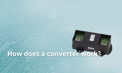 Kaip veikia keitiklis?
Jūsų atsiliepimo įvertinimas negali būti išsiųstas
Pranešti apie komentarą
Pranešimas apie atsiliepimą išsiųstas
Jūsų pranešimas apie atsiliepimą neišsiųstas
Parašyti savo atsiliepimą
Atsiliepimas išsiųstas
Jūsų atsiliepimas neišsiųstas
