Jūs turite būti prisijungę
Neturite paskyros?
Category
Spintų montavimas
Spintelių projektavimas ir surinkimas
Maitinimo sistemų montavimas
Komponentai
Mašinos, pagamintos pagal užsakymą
MTEP mokslinių tyrimų ir plėtros darbas
Pramoniniai testeriai
Induktyvumo ričių aptarnavimas ir regeneracija
Induktoriaus atnaujinimas
Naujų induktorių gamyba
Žinių bazė
Indukcinio kaitinimo generatoriai
Remontas ir modernizavimas
Išoriniai įrenginiai
Panaudojimo pavyzdžiai
Pramoninių vandens aušintuvų ir oro kondicionierių aptarnavimas
Mašinų remontas ir modernizavimas
Pramoninės elektronikos įrenginių remontas
Aukštos įtampos maitinimo šaltiniai elektrostatiniams filtrams – KraftPowercon
Pramoniniai spausdintuvai ir etikiečių spausdintuvai
UDT sertifikatas
Nuotraukos yra skirtos tik informaciniams tikslams. Peržiūrėkite produkto specifikaciją
please use latin characters
Ar Jūs domina šis produktas? Ar Jums reikia papildomos informacijos ar individualaus pasiūlymo?
Enim quis fugiat consequat elit minim nisi eu occaecat occaecat deserunt aliquip nisi ex deserunt.
Pridėti į norų sąrašą
tu turi būti prisijungęs
Jūsų atsiliepimo įvertinimas negali būti išsiųstas
Pranešti apie komentarą
Pranešimas apie atsiliepimą išsiųstas
Jūsų pranešimas apie atsiliepimą neišsiųstas
Parašyti savo atsiliepimą
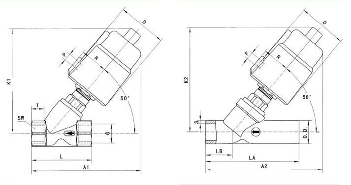
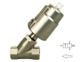
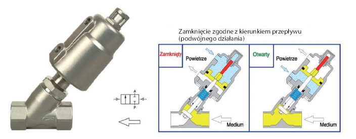
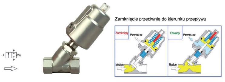
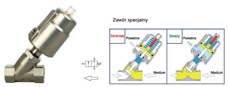
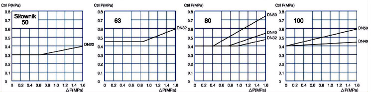
Kampiniai vožtuvai
Aš sutinku su bendrosiomis naudojimo sąlygomis ir privatumo politika. *
* Privalomi laukai
Atsiliepimas išsiųstas
Jūsų atsiliepimas neišsiųstas
This store asks you to accept cookies for performance, social media and advertising purposes. Social media and advertising cookies of third parties are used to offer you social media functionalities and personalized ads. Do you accept these cookies and the processing of personal data involved?