Application
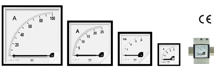
MA16, MB16, MA17, MA19 and MA12 moving-coil meters are intended for measuring d.c. voltage or d.c. current. These meters with built rectifiers can also be used for measuring a.c. voltages and a.c. currents. MA17P, MA19P, MA12P meters with built-in rectifiers are used for measurement of the rectified current or voltage arithmetical mean value and they are such calibrated that they indicate the RMS value at sinusoidal curve shape. The measurement of non-sinusoidal a.c. magnitudes results in additional errors.
MA16, MA17, MA17P, MA19, MA19P, MA12 and MA12P meters are designed for mounting into panels. MB16 meters are adapted for a fast assembly rail mounting (35 mm rail) in compliance with EN 60715 standard MA16, MA17 and MA19 meters are designed for interchangeable dials..
TECHNICAL DATA
| Accuracy class |
1.5 |
| Internal resistance, voltage drop, current or power consumption |
acc. tables 1, 2 and 3 |
| Adaptation of the meter measuring range to the range of interchangeable shunts or measuring transducers |
by changing of the dial: the dial is simply extracted with a suitable tool and replaced through the upper
slot of the case
Note: MA12 (144 x 144) meters are not provided for interchangeable dials |
Categories of meter climatic versions
If it is not written otherwise in the order, these meters are intended to use in moderate climatic conditions. Then, we do not place any symbol on the scale. On customers’ request, meters can be adapted to use in conditions of a dry or wet tropical climat. Then, they are marked with the T III symbol.
Requirements concerning safety acc. EN 61010-1 standard: For MA16 and MB16 meters and meters with rectifiers:
| - maximal phase-earth working voltage |
600 V |
| - installation category |
III |
| - pollution degree |
2 |
For MA17, MA19 and MA12 meters:
| - maximal phase-earth working voltage |
600V |
| - installation category |
III |
| - pollution degree |
2 |
Protection Grade acc. to EN 60529
| - in standard opton: |
IP 50 for MA16, MA17, MA17P, MA19, MA19P, MA12, MA12P meters |
| |
|
IP 54 (only for MA12 and MA12P meters) |
| |
|
IP 52 (only for MB16 meter) |
| - with IP 65 front protection grade (on request): |
IP 20 terminal protection (with a terminal protective cover) |
| Case material |
thermoplastic material |
| Meter glass material |
glass |
| Additional setting pointer |
On customers request MA17 and MA19 meters can be equiped with an additional, setting red pointer fixed on the glass. |
ACCESSORIES
We deliver with the meter:
- screw holders (for standard options)............. 2 pcs
- screw holders (for IP65 option)..................... 4 pcs
- terminal protection cover............................... 1 pc
- spring holders (only for MA16)...................... 2 pcs
Note: MB16 meters do not have terminal protective cover.
We can also deliver on request, interchangeable shunts of B2, B3,
B4, B5 and B5 types.
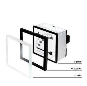
Dc current and dc voltage ranges, internal resistance or voltage drop
Frontal frame
dimensions [mm] |
48 x 48*' |
72 x 72 |
96 x 96 |
144x144 |
| Scale length [mm] |
42 |
61 |
95 |
160 |
| Weight [kg] |
0,15 |
0,2 |
0,25 |
0,4 |
| Type |
MA16, MB16 |
MA17 |
MA19 |
MA12 |
| Internal resistance 20%, voltage drop or current consumption |
Measuring
range |
zero on the side of the scale |
zero in the middle of the scale |
zero on the side of the scale |
zero in the middle of the scale |
zero on the side of the scale |
zero in the middle of the scale |
zero on the side of the scale |
zero in the middle of the scale |
| 40 µA |
6,7 kΩ |
6,7 kΩ |
|
|
|
|
|
|
| 60 µA |
6,7 kΩ |
2,465 kΩ |
|
|
|
|
|
|
| 100 µA |
2,468 kΩ |
1,098 kΩ |
5 kΩ |
2,2 kΩ |
5 kΩ |
2,2 kΩ |
5,8 kΩ |
5,8 kΩ |
| 150 µA |
2,468 kΩ |
1,098 kΩ |
5 kΩ |
2,2 kΩ |
5 kΩ |
2,2 kΩ |
5,8 kΩ |
2,6 kΩ |
| 250 µA |
1,097 kΩ |
387 Ω |
2,2 kΩ |
580 Ω |
2,2 kΩ |
580 Ω |
2,6 kΩ |
1,04 kΩ |
| 400 µA |
387 Ω |
147 Ω |
1,6 kΩ |
225 Ω |
1,6 kΩ |
225 Ω |
1,04 kΩ |
287 Ω |
| 600 µA |
147 Ω |
70 Ω |
573 Ω |
78,3 Ω |
573 Ω |
78,3 Ω |
753 Ω |
238 Ω |
| 1 mA |
70 Ω |
69,7 Ω |
225 Ω |
173 Ω |
225 Ω |
173 Ω |
238 Ω |
236 Ω |
| 1,5 mA |
35 Ω |
14,1 Ω |
76,7 Ω |
17,4 Ω |
76,7 Ω |
17,4 Ω |
69 Ω |
69 Ω |
| 2,5 mA |
14,1 Ω |
6 Ω |
20,8 Ω |
9,2 Ω |
20,8 Ω |
9,2 Ω |
69 Ω |
13,5 Ω |
| 4 mA |
6 Ω |
4,5 Ω |
16,5 Ω |
9,3 Ω |
16,5 Ω |
9,3 Ω |
18,2 Ω |
5,2 Ω |
| 5 mA |
4 Ω |
4,5 Ω |
12,4 Ω |
3,0 Ω |
12,4 Ω |
3,0 Ω |
14,5 Ω |
6,1 Ω |
| 6 mA |
4 Ω |
4,5 Ω |
9,2 Ω |
3,0 Ω |
9,2 Ω |
3,0 Ω |
14,5 Ω |
3,2 Ω |
| 10 mA |
2,65 Ω |
2,6 Ω |
3,3 Ω |
2,2 Ω |
3,3 Ω |
2,2 Ω |
6,1 Ω |
2,1 Ω |
| 15 mA |
2,5 Ω |
2,1 Ω |
2,7 Ω |
2,0 Ω |
2,7 Ω |
2,0 Ω |
3,2 Ω |
2,1 Ω |
| 20 mA |
2,5 Ω |
2,1 Ω |
2,0 Ω |
1,4 Ω |
2,0 Ω |
1,4 Ω |
2,1 Ω |
1,29 Ω |
| 25 mA |
60 mV |
2,1 Ω |
1,4 Ω |
2,1 Ω |
1,4 Ω |
2,1 Ω |
1,3 Ω |
| 40 mA |
60 mV |
60 mV |
60 mV |
60 mV |
| 60 mA |
60 mV |
60 mV |
60 mV |
60 mV |
| 100 mA |
60 mV |
60 mV |
60 mV |
60 mV |
| 150 mA |
60 mV |
60 mV |
60 mV |
60 mV |
| 250 mA |
60 mV |
60 mV |
60 mV |
60 mV |
| 400 mA |
60 mV |
60 mV |
60 mV |
60 mV |
| 600 mA |
60 mV |
60 mV |
60 mV |
60 mV |
| 1:00 AM |
60 mV |
60 mV |
60 mV |
60 mV |
| 1,5 A |
60 mV |
60 mV |
60 mV |
60 mV |
| 2,5 A |
60 mV |
60 mV |
60 mV |
60 mV |
| 4:00 AM |
60 mV |
60 mV |
60 mV |
60 mV |
| 6:00 AM |
60 mV |
60 mV |
60 mV |
60 mV |
| 10:00 AM |
60 mV |
60 mV |
60 mV |
60 mV |
| 15 A |
60 mV |
60 mV |
60 mV |
60 mV |
| 20 A |
60 mV |
60 mV |
60 mV |
60 mV |
| 25 A |
60 mV |
60 mV |
60 mV |
60 mV |
| 4...20 mA |
2,44 Ω |
2,7 Ω |
2,7 Ω |
|
| For shunt connection |
| ... A/60 mV |
6 Ω |
6 Ω |
6 Ω |
6 Ω |
| ...A/150 mV |
30 Ω |
30 Ω |
30 Ω |
30 Ω |
| 60 mV |
6 Ω |
6 Ω |
6 Ω |
6 Ω |
| 100 mV |
10 Ω |
10 Ω |
10 Ω |
10 Ω |
| 150 mV |
30 Ω |
29 Ω |
29 Ω |
35 Ω |
| 250 mV |
55 Ω |
62 Ω |
62 Ω |
60 Ω |
| 400 mV |
400 Ω |
260 Ω |
260 Ω |
248 Ω |
| 600 mV |
604 Ω |
400 Ω |
400 Ω |
386 Ω |
| Type |
MA16, MB16 |
MA17 |
MA19 |
MA12 |
| Internal resistance 20%, voltage drop or current consumption |
Measuring
range |
zero on the side of the scale |
zero in the middle of the scale |
zero on the side of the scale |
zero in the middle of the scale |
zero on the side of the scale |
zero in the middle of the scale |
zero on the side of the scale |
zero in the middle of the scale |
| 1 V |
1000 Ω/V |
1000 Ω/V |
1000 Ω/V |
1000 Ω/V |
| 1,5 V |
1000 Ω/V |
1000 Ω/V |
1000 Ω/V |
1000 Ω/V |
| 2,5 V |
1000 Ω/V |
1000 Ω/V |
1000 Ω/V |
1000 Ω/V |
| 4 V |
1000 Ω/V |
1000 Ω/V |
1000 Ω/V |
1000 Ω/V |
| 6 V |
1000 Ω/V |
1000 Ω/V |
1000 Ω/V |
1000 Ω/V |
| 10 V |
1000 Ω/V |
1000 Ω/V |
1000 Ω/V |
1000 Ω/V |
| 15 V |
1000 Ω/V |
1000 Ω/V |
1000 Ω/V |
1000 Ω/V |
| 25 V |
1000 Ω/V |
1000 Ω/V |
1000 Ω/V |
1000 Ω/V |
| 40 V |
1000 Ω/V |
1000 Ω/V |
1000 Ω/V |
1000 Ω/V |
| 60 V |
1000 Ω/V |
1000 Ω/V |
1000 Ω/V |
1000 Ω/V |
| 100 V |
1000 Ω/V |
1000 Ω/V |
1000 Ω/V |
1000 Ω/V |
| 150 V |
1000 Ω/V |
1000 Ω/V |
1000 Ω/V |
1000 Ω/V |
| 250 V |
1000 Ω/V |
1000 Ω/V |
1000 Ω/V |
1000 Ω/V |
| 300 V |
1000 Ω/V |
1000 Ω/V |
1000 Ω/V |
1000 Ω/V |
| 400 V |
1000 Ω/V |
1000 Ω/V |
1000 Ω/V |
1000 Ω/V |
| 500 V |
1000 Ω/V |
1000 Ω/V |
1000 Ω/V |
1000 Ω/V |
| 600 V |
1000 Ω/V |
1000 Ω/V |
1000 Ω/V |
1000 Ω/V |
| 800 V |
1000 Ω/V |
1000 Ω/V |
1000 Ω/V |
1000 Ω/V |
| 1000 V |
1000 Ω/V |
1000 Ω/V |
1000 Ω/V |
1000 Ω/V |
| To co-operate with an external resistor D2 |
| 1500 V |
- |
1000 Ω/V |
1000 Ω/V |
1000 Ω/V |
| 2500 V |
- |
1000 Ω/V |
1000 Ω/V |
1000 Ω/V |
*) Concerns MA16 meters: frontal dimensions, see fig.1
Dc measuring ranges with external shunts
|
1 A, 1,5 A, 2,5 A , 4 A, 6 A
10 A, 15 A, 25 A, 40 A, 60 A, 100 A, 150 A, 250 A, 400 A, 600 A, 1 kA, 1,5 kA, 2,5 kA, 4 kA, 6 kA, 10 kA, 15 kA
|
1. Measuring movement current considerated when calibrating
shunts:
B2 - 60 mV – 10 mA
B3 - 150 mV – 5 mA
2. Resistance of conductors linking the meter with the shunt:
0.035 W
3. After agreeing with the producer it is possible to offer shunts
with following standarized voltage drops: 50 mV, 75 mV, 100 mV
4. Further particulars on shunts are contained in the catalogue:
Interchangeable shunts |
Ac measuring ranges
Frontal frame
dimensions [mm] |
72 x 72 |
96 x 96 |
144x144 |
Notes |
| Scale length [mm] |
61 |
95 |
160 |
| Weight [kg] |
0,2 |
0,25 |
0,4 |
| Type |
MA17P |
MA19P |
MA12P |
| Measuring range |
Drop voltage or power consumption (self-consumption) |
| 400 µA |
1,7 V |
1,7 V |
1,6 V |
Rated operational
range for frequency
30...1000...10 000 Hz |
| 600 µA |
| 1 mA |
| 1,5 mA |
| 2,5 mA |
| 4 mA |
| 6 mA |
| 10 mA |
| 15 mA |
| 25 mA |
| 40 mA |
| 60 mA |
| 100 mA |
| 150 mA |
| 250 mA |
| 400 mA |
| 500 mA |
| 2,5 mA |
| 600 mA |
| 1 A |
| 1A |
5 mW |
5 mW |
- |
Rated operational
range for frequency
49...50...51 Hz
|
| 1,5 A |
7 mW |
7 mW |
- |
| 2,5 A |
12 mW |
12 mW |
- |
| 4 A |
19 mW |
19 mW |
- |
| 5 A |
21 mW |
21 mW |
- |
| 6 A |
23 mW |
23 mW |
- |
| 60 mV |
3 mW |
3 mW |
- |
| 100 mV |
3 mW |
3 mW |
- |
| 150 mV |
3 mW |
3 mW |
- |
| 250 mV |
3 mW |
3 mW |
- |
| 400 mV |
3 mW |
3 mW |
- |
| 600 mV |
3 mW |
3 mW |
- |
| 1 V |
3 mW |
3 mW |
- |
| 1,5 V |
3 mW |
3 mW |
- |
| 2,5 V |
1000 W/V |
1000 W/V |
1000 W/V |
Rated operational
range for frequency
30...1000...10 000 Hz |
| 4 V |
| 6 V |
| 10 V |
| 15 V |
| 25 V |
| 40 V |
| 60 V |
| 100 V |
| 150 V |
| 250 V |
| 400 V |
| 500 V |
| 600 V |
ORDERING PROCEDURE
In the order one must specify: name and type of meter, measuring range, shunt data if the meter is foressen to co-operate with an interchangeable shunt, working position, kind of climat (only for tropical versions), kind of holders and eventual additional requirements. One must order interchangeable shunts or D2 series resistors. When ordering meters for measuring a.c. current or a.c. voltage, one must add to the meter name „rectifier” - (rectifier meter)
Example of order:
MA16 ammeter, 40 A, c2 30, TIII, screw holders, 0…40 A range
IP54, B2/60 mV- 40 A shunt, IP65.
MA16 – moving-coil meter (48 x 48 mm),
40 A – 40 A range,
c2 30 – working position 30° with relation to horizontal position
(table 4),
TIII – design and materials adapted to specific tropical klimat,
Screw holders – type of holders (screw or spring-holders),
0…40 A – measuring range on the dial,
B2/60 mV/ 40 A – to co-operate with a 40 A shunt of B2 type
IP 54 – protection grade of the casting front
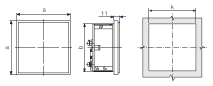
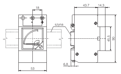 Fig . 1. External dimensions of MB16
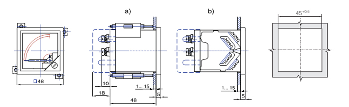
Fig. 2. External dimensions of MA16 meters
a) with screw holders
b) with spring holders
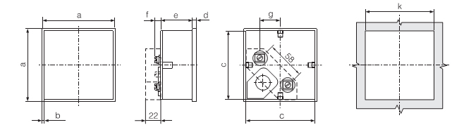
| Type |
a |
b |
c |
d |
e |
f |
g |
k |
| |
mm |
MA17, MA17P
|
72 |
4 |
68-0,3 |
5 |
45 |
10... 20 |
20,5 |
68+0,7 |
MA19, MA19P
|
96 |
4 |
92-0,3 |
5 |
45 |
0. 2 O |
32,5 |
92+0,8 |
MA12, MA12P
|
144 |
4,5 |
137,3-05 |
6 |
48 |
10... 20 |
55,5 |
138+10 |
Fig. 3. External dimensions of MA17, MA19 and MA12 meters
 |
 |
| Type |
a |
b |
k |
MA16
|
58 |
47 |
47,2+0,6 |
MA17, MA17P
|
81 |
70 |
70,2+0,7 |
MA19, MA19P
|
105 |
94 |
94,2+0,8 |
|
• MA16 meters
The meters are adapted to be mounted from the front of panels and then they are equiped with two spring holders, which can be fixed on arbitrary opposite case sides (Fig. 1b) or to be mounted from the rear of panels and then they are equiped with two screw holders which can be fixed on arbitrary, opposite case corners (Fig. 1a).
• MA17, MA19 and MA12 meters
In their basic execution these meters are adapted to be mounted from the rear of panels by means of two screw holders which can be fixed on arbitrary opposite case corners (Fig. 5).
• Execution of meters with IP 65 - The meter is fixed in the panel by means of 4 screw holders.
After agreeing with the manufacturer, MA17 and MA19 meters can be delivered with a snap fastened frontal frame and then these meters can be mounted from the front of panels by means of two spring holders fixed on arbitrary opposite case sides.
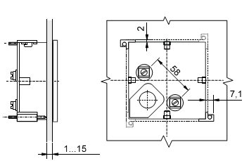
Fig. 5. Fixing of meters in the panel
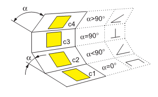
| Kod |
Working position |
| 0 |
c3 α = 90° |
| A |
c1 α = 0° |
| B |
c2, α = 15° |
| C |
c2, α = 30° |
| D |
c2, α = 45° |
| E |
c2, α = 60° |
| F |
c2, α = 75° |
| H |
c4, α = 105° |
| I |
c4, α = 120° |