The technique of moulding conductive elastomers has a wide range of benefits. This process allows T C Shielding to manufacture components that have a very accurate tolerance requirement. Below is a list of its major advantages:
Odd and 3D shaped components are easily made.
Accurate tolerances can be held.
Small products are easy to manufacture.
Product can be adhesive backed (dependent upon moulding type).
Silicones and fluorosilicones plus wide range of conductive fillers.
Comparative Properties - Moulded Materials
General Description
EcE Material Reference (Type)
1A
1B
1D
1F
1G
1I
Elastomer Type (Sil - Silicone, F/Sil - Fluorosilicone)
Sil
Sil
Sil
Sil
Sil
Sil
Filler Material
Ag/Ni
Ag/Cu
Ag/Al
Carbon
Ag
Ag/Glass
Colour
Tan
Tan
Tan
Black
Tan
Tan
Electrical Properties
Tol
Test Method
Volume Resistivity (ohm.cm)
Max
0,005
0,005
0,008
9,000
0,002
0,005
Shielding Effectiveness (dB) 200 KHz (H-Field)
MIL-G-83528 MIL 285
70
70
70
30
70
55
100 MHz (E-Field)
105
115
110
65
115
95
500 MHz (E-Field)
105
115
105
60
115
95
2 GHz (Plane Wave)
100
115
100
40
115
95
10 GHz (Plane Wave)
100
115
100
30
115
95
Physical Properties
Specific Gravity (g/cm∆)
±5%
ASTM D-792
3,71
3,32
2,19
1,19
3,20
"2.00 75 1.25"
Hardness (Shore A)
± 5
ASTM D-2240
70
75
70
70
75
Tensile Strength (MPa)
Min
ASTM D-412
1,25
1,25
1,25
5,00
1,25
Elongation (%)
Min
ASTM D-412
100
100
100
150
100
100
Compression Set (%)
Max
ASTM D-395
30
30
30
20
30
30
Upper Operating Temperature (°C)
-
160
125
160
160
160
160
Lower Operating Temperature (°C)
-
ASTM D-1329
-50
-50
-50
-50
-50
-50
General Description
EcE Material Reference (Type)
1J
1J/8
2A
2B
2D
2J
Non Flam
Elastomer Type (Sil - Silicone, F/Sil - Fluorosilicone)
Sil
Sil
F/Sil
F/Sil
F/Sil
F/Sil
Filler Material
Ni/Gr
Ni/Gr
Ag/Ni
Ag/Cu
Ag/Al
Ni/Gr
Colour
szary
szary
Tan
Tan
Green
Green
Electrical Properties
Tol
Test Method
Volume Resistivity (ohm.cm)
Max
0,05
"0.050-
0,005
0,005
0,01
0,05
0.100"
Shielding Effectiveness (dB)
MIL-G-83528
200 KHz (H-Field)
MIL 285
70
70
75
75
70
70
100 MHz (E-Field)
95
95
110
110
110
100
500 MHz (E-Field)
90
90
110
120
105
100
2 GHz (Plane Wave)
90
90
105
120
100
100
10 GHz (Plane Wave)
90
90
100
120
100
100
Physical Properties
Specific Gravity (g/cm∆)
±5%
ASTM D-792
2,45
2,3
4,6
5
2,7
3,25
Hardness (Shore A)
± 5
ASTM D-2240
80
75
80
75
70
80
Tensile Strength (MPa)
Min
ASTM D-412
2
1,4
1,25
1,25
0,55
0,75
Elongation (%)
Min
ASTM D-412
150
125
100
100
100
100
Compression Set (%)
Max
ASTM D-395
30
30
30
30
30
30
Upper Operating Temperature (°C)
-
160
160
160
125
160
160
Lower Operating Temperature (°C)
-
ASTM D-1329
-50
-50
-50
-55
-55
-55
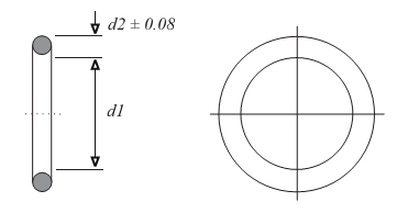
Standard connector products
Rear Mounting Jam Nut Receptacle ‘O’ Rings
Shell size
MIL C 38999 MIL C 26482
MIL C 81511
d1
Tol d1 ±
d2
TC REF
TC REF
mm
mm
mm
6
1
-
14.00
0.13
1.78
8
2
-
17.16
0.13
1.78
8
-
3
18.77
0.13
1.78
9
4
-
20.35
0.15
1.78
10
-
5
21.95
0.15
1.78
11+12
6
-
25.12
0.15
1.78
13+14
7
7
28.30
0.15
1.78
15+16
8
8
31.47
0.15
1.78
17+18
9
9
34.65
0.15
1.78
19+20
10
-
37.77
0.15
2.62
21+22
11
-
40.95
0.25
2.62
23+24
12
-
44.12
0.25
2.62
Order example
MA - XX - XXX Example: MA
MA - Moulded Ring 3A - Silver Aluminium/Silicone 001 - Shell size
Cost Effective Alternative To Conductive Moulded O-Rings
T.C.Shielding have developed a range of extruded/jointed O-Rings that offer a cost effective alternative to traditionally moulded items with added benefits, and compatible tolerancing. The following are benefits of this new process.
Low tooling cost
Reduced production scrap rate
Advantage of hollow forms which help to reduce compression force
Zero flash on profile
Compatible tolerancing
Shorter lead times
Minimum ID of 18.00mm
Below is a comparison between moulded and jointed tolerances
Moulded O-ring ID = 25.12+/-0.15 Section = 1.78+/-0.08 Developed Lenght= 84.04/84.98
Ext./Jointed O-ring ID = 25.12+/-0.16 Cross section= 1.78+/-0.10 Developed Length= 84.00/85.00
The technique of moulding conductive elastomers has a wide range of benefits. This process allows T C Shielding to manufacture components that have a very accurate tolerance requirement. Below is a list of its major advantages:
Odd and 3D shaped components are easily made.
Accurate tolerances can be held.
Small products are easy to manufacture.
Product can be adhesive backed (dependent upon moulding type).
Silicones and fluorosilicones plus wide range of conductive fillers.
Comparative Properties - Moulded Materials
General Description
EcE Material Reference (Type)
1A
1B
1D
1F
1G
1I
Elastomer Type (Sil - Silicone, F/Sil - Fluorosilicone)
Sil
Sil
Sil
Sil
Sil
Sil
Filler Material
Ag/Ni
Ag/Cu
Ag/Al
Carbon
Ag
Ag/Glass
Colour
Tan
Tan
Tan
Black
Tan
Tan
Electrical Properties
Tol
Test Method
Volume Resistivity (ohm.cm)
Max
0,005
0,005
0,008
9,000
0,002
0,005
Shielding Effectiveness (dB) 200 KHz (H-Field)
MIL-G-83528 MIL 285
70
70
70
30
70
55
100 MHz (E-Field)
105
115
110
65
115
95
500 MHz (E-Field)
105
115
105
60
115
95
2 GHz (Plane Wave)
100
115
100
40
115
95
10 GHz (Plane Wave)
100
115
100
30
115
95
Physical Properties
Specific Gravity (g/cm∆)
±5%
ASTM D-792
3,71
3,32
2,19
1,19
3,20
"2.00 75 1.25"
Hardness (Shore A)
± 5
ASTM D-2240
70
75
70
70
75
Tensile Strength (MPa)
Min
ASTM D-412
1,25
1,25
1,25
5,00
1,25
Elongation (%)
Min
ASTM D-412
100
100
100
150
100
100
Compression Set (%)
Max
ASTM D-395
30
30
30
20
30
30
Upper Operating Temperature (°C)
-
160
125
160
160
160
160
Lower Operating Temperature (°C)
-
ASTM D-1329
-50
-50
-50
-50
-50
-50
General Description
EcE Material Reference (Type)
1J
1J/8
2A
2B
2D
2J
Non Flam
Elastomer Type (Sil - Silicone, F/Sil - Fluorosilicone)
Sil
Sil
F/Sil
F/Sil
F/Sil
F/Sil
Filler Material
Ni/Gr
Ni/Gr
Ag/Ni
Ag/Cu
Ag/Al
Ni/Gr
Colour
szary
szary
Tan
Tan
Green
Green
Electrical Properties
Tol
Test Method
Volume Resistivity (ohm.cm)
Max
0,05
"0.050-
0,005
0,005
0,01
0,05
0.100"
Shielding Effectiveness (dB)
MIL-G-83528
200 KHz (H-Field)
MIL 285
70
70
75
75
70
70
100 MHz (E-Field)
95
95
110
110
110
100
500 MHz (E-Field)
90
90
110
120
105
100
2 GHz (Plane Wave)
90
90
105
120
100
100
10 GHz (Plane Wave)
90
90
100
120
100
100
Physical Properties
Specific Gravity (g/cm∆)
±5%
ASTM D-792
2,45
2,3
4,6
5
2,7
3,25
Hardness (Shore A)
± 5
ASTM D-2240
80
75
80
75
70
80
Tensile Strength (MPa)
Min
ASTM D-412
2
1,4
1,25
1,25
0,55
0,75
Elongation (%)
Min
ASTM D-412
150
125
100
100
100
100
Compression Set (%)
Max
ASTM D-395
30
30
30
30
30
30
Upper Operating Temperature (°C)
-
160
160
160
125
160
160
Lower Operating Temperature (°C)
-
ASTM D-1329
-50
-50
-50
-55
-55
-55
Standard connector products
Rear Mounting Jam Nut Receptacle ‘O’ Rings
Shell size
MIL C 38999 MIL C 26482
MIL C 81511
d1
Tol d1 ±
d2
TC REF
TC REF
mm
mm
mm
6
1
-
14.00
0.13
1.78
8
2
-
17.16
0.13
1.78
8
-
3
18.77
0.13
1.78
9
4
-
20.35
0.15
1.78
10
-
5
21.95
0.15
1.78
11+12
6
-
25.12
0.15
1.78
13+14
7
7
28.30
0.15
1.78
15+16
8
8
31.47
0.15
1.78
17+18
9
9
34.65
0.15
1.78
19+20
10
-
37.77
0.15
2.62
21+22
11
-
40.95
0.25
2.62
23+24
12
-
44.12
0.25
2.62
Order example
MA - XX - XXX Example: MA
MA - Moulded Ring 3A - Silver Aluminium/Silicone 001 - Shell size
Cost Effective Alternative To Conductive Moulded O-Rings
T.C.Shielding have developed a range of extruded/jointed O-Rings that offer a cost effective alternative to traditionally moulded items with added benefits, and compatible tolerancing. The following are benefits of this new process.
Low tooling cost
Reduced production scrap rate
Advantage of hollow forms which help to reduce compression force
Zero flash on profile
Compatible tolerancing
Shorter lead times
Minimum ID of 18.00mm
Below is a comparison between moulded and jointed tolerances
Moulded O-ring ID = 25.12+/-0.15 Section = 1.78+/-0.08 Developed Lenght= 84.04/84.98
Ext./Jointed O-ring ID = 25.12+/-0.16 Cross section= 1.78+/-0.10 Developed Length= 84.00/85.00