In resistance welding machines, replacement of the ignitron contactors with thyristor contactors is performed. If we consider electrical connections, the thyristor contactor circuit (a suitable module block) only requires a circuit for matching the ignitron triggering pulses to the level of pulses necessary for triggering the thyristors, so there are no technical contraindications here. The appropriate matching circuit is shown in Fig. 3. The output of Z1 circuit should be connected to the tip removed from the ignitron starter, while B1 and K1 points should be connected to the gate and cathode of T1 thyristors. Mechanical mounting of thyristor contactor does not cause any changes in construction of the welding machine. The existing water cooling system of the ignitrons is also used. To ensure proper operation of the module block in the thyristor contactor system in the welder, it is necessary to maintain the existing water block in the ignitron system.
Technical data
Modular block type
Range VDRM [V]
ITSM [A]
I2t [A2s]
IGT [mA]
A2Q6W - 125 - ...
1200-2200
3000
45000
150
A2Q6W - 200 - ...
1200-2200
3600
65000
A2Q6W - 300 - ...
1200-1600
5000
125000
A2Q7W - 350 - ...
1200-2200
6300
200000
300
A2Q7W - 450 - ...
1200-2200
7600
290000
A2Q7W - 550 - ...
1200-1800
9100
290000
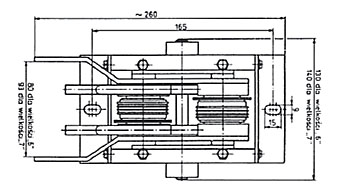
Fig. 1. Table of connections of welding modules - block type A2Q.W
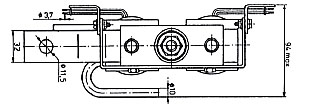
Fig. 2. Two-thyristor block for welding machines
„6" - thyristor thickness approx. 15 mm „7" - thyristor thickness approx. 26 mm
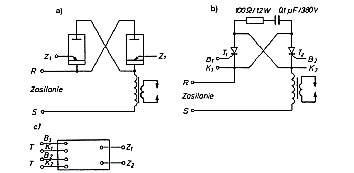
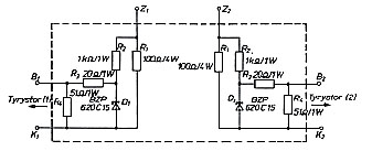
Fig. 3. The principle of using a two-thyristor modular block as a replacement for an ignitor contactor in a welding machine
a) ignitron system, b) thyristor contactor system, c) matching system.
In resistance welding machines, replacement of the ignitron contactors with thyristor contactors is performed. If we consider electrical connections, the thyristor contactor circuit (a suitable module block) only requires a circuit for matching the ignitron triggering pulses to the level of pulses necessary for triggering the thyristors, so there are no technical contraindications here. The appropriate matching circuit is shown in Fig. 3. The output of Z1 circuit should be connected to the tip removed from the ignitron starter, while B1 and K1 points should be connected to the gate and cathode of T1 thyristors. Mechanical mounting of thyristor contactor does not cause any changes in construction of the welding machine. The existing water cooling system of the ignitrons is also used. To ensure proper operation of the module block in the thyristor contactor system in the welder, it is necessary to maintain the existing water block in the ignitron system.
Technical data
Modular block type
Range VDRM [V]
ITSM [A]
I2t [A2s]
IGT [mA]
A2Q6W - 125 - ...
1200-2200
3000
45000
150
A2Q6W - 200 - ...
1200-2200
3600
65000
A2Q6W - 300 - ...
1200-1600
5000
125000
A2Q7W - 350 - ...
1200-2200
6300
200000
300
A2Q7W - 450 - ...
1200-2200
7600
290000
A2Q7W - 550 - ...
1200-1800
9100
290000
Fig. 1. Table of connections of welding modules - block type A2Q.W
Fig. 2. Two-thyristor block for welding machines
„6" - thyristor thickness approx. 15 mm „7" - thyristor thickness approx. 26 mm
Fig. 3. The principle of using a two-thyristor modular block as a replacement for an ignitor contactor in a welding machine
a) ignitron system, b) thyristor contactor system, c) matching system.