| Technical data |
SNZ 4052K |
Function according to EN 574-1
|
|
|
|
|
|
|
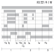
FD 221-9-1 W
|
|
|
|
|
|
24 V
|
|
|
|
Rated voltage Un AC
|
|
115 - 120 V
|
230 V
|
|
Rated consumption at 50 Hz i Un (AC)
|
3,1 VA
|
2,4 VA
|
2,4 VA
|
|
Rated consumption at 50 Hz i Un (AC)
|
1,9 W
|
2,2 W
|
2,2 W
|
|
Rated consumption at Un (DC)
|
2,4 W
|
-
|
-
|
|
|
2,4 Vss
|
|
|
|
Electrical isolation supply circuit – control circuit
|
no
|
yes
|
yes
|
Fuse for control circuit supply
|
PTC thermistor
|
Short-circuit proof transformer
|
Short-circuit proof transformer
|
|
Residual ripple Uss
|
2,4 V
|
|
|
50 - 60 Hz
|
|
|
0,85 - 1,1x UN
|
|
|
|
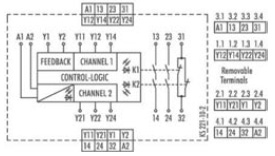
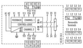
Rated output voltage (Y12 / Y14 or Y22 / Y24 and Y1), only for supply of inputs Y11, Y21 and Y2
|
DC 24 V
|
|
Response time tE for K1, K2
|
40 ms
|
|
Release time tA
|
< 50 ms
|
|
Synchronous monitoring time tS
|
500 ms
|
|
Recovery time tW
|
250 ms
|
|
|
|
|
|
2 enabling current paths, positively driven contacts (NO contact), 1 signaling current path (NC contact)
|
|
Rated operating voltage Un
|
AC/DC 230 V
|
Max. continuous current In per contact
|
6 A
|
|
Max. total current of all current paths AC/DC 24 V
AC 115 - 120 V, AC 230 V
|
12 A
8 A
|
|
Application category according to EN 60947-5-1
|
AC-15: Ue 230 V AC, Ie 4 A (360 switching cycles//h)
DC-13: Ue 24 V DC, Ie 5 A (360 switching cycles//h)
|
Short-circuit protection, max. fuse insert
|
6 A class gG or circuit breaker with trigger characteristic B or C
|
|
|
10x106 switching cycles
|
|
|
|
|
Creepage distances and clearances between the circuits
|
według EN 60664-1
|
|
|
III
|
|
|
4 kV
|
|
|
AC 300 V
|
|
|
|
|
Protection degree according to DIN EN 60529 (housing / terminals)
|
IP 40/IP 20
|
Ambient temperature / storage temperature
|
-25 - +55 °C/-25 - +75 °C
|
|
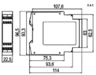
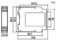
Dimension diagram
|
K 4-1 (screw terminals / K 4-2 (pluggable terminals)
|
Rated cross sections fine-stranded/solid
or fine-stranded with ferrules
|
2x0,14 - 0,75 mm2/1x0,14 - 2,5 mm2
1x0,25 - 2,5 mm2/2x0,25 - 0,5 mm2
|
Permissible tightening torque
|
0,5 - 0,6 Nm
|
|
for UL and CSA applications Wire ranges Max. tightening torques
|
AWG 18-16 only use Cu wires
0.79 in-lbs
|
|
Weight
|
0,20 kg (device DC) / 0,25 kg (device AC)
|
|
Accessories
|
-
|