
Vous devez être connecté
Category


Les photos sont à titre informatif uniquement. Voir les spécifications du produit
please use latin characters
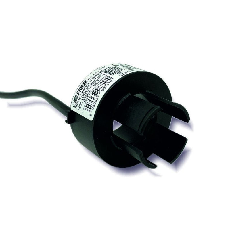
The TDC and TDA series are current transformers designed for use with [Type A-F Earth Leakage Relays].
They must be installed with all single- or three-phase network conductors (phases and neutral, if present) routed inside the core. The protective conductor (PE or PEN) (for TN-C systems) must be located outside the core. The connection between the transformer and the leakage current relay must be made using the shortest possible length of shielded cable (shield grounded at one end) and routed at a significant distance from power circuits to minimize coupling interference and voltage drops on the resistances of the supply conductors.
| Parameter | Value |
|---|---|
| Self estinguishing (Thermoplastic material) | UL 90-V0 |
| Operating frequency | 47-63Hz |
| Insulation | 2,5kV 50Hz, 1 min. |
| Protection degree | IP20 |
| Continuous overload | 1000A |
| Thermal overload (1s) | 40kA |
| Operating temperature | 0…+50˚C U.R./R.H. < 90% n.c. |
| Storage temperature | -20…+70˚C |
| Connections | Screw, max 1,6mm2 |
| Code | Core | Figure | A | B | C | D | E | F | G | H | I | kg |
|---|---|---|---|---|---|---|---|---|---|---|---|---|
| TDC032 | Closed | Figure 1. | 0,3 | |||||||||
| TDC028 | Figure 2. | 0,1 | ||||||||||
| TDC035 | Fig. 3 | 35 | 102 | 73 | 92 | 100 | - | 40 | 6 | 28 | 0,2 | |
| TDC060 | Fig. 3 | 60 | 135 | 98 | 116 | 125 | - | 55 | 6 | 28 | 0,2 | |
| TDC080 | Fig. 3 | 80 | 154 | 118 | 136 | 146 | - | 65 | 6 | 38 | 0,4 | |
| TDC110 | Fig. 3 | 110 | 180 | 148 | 166 | 178 | - | 85 | 6 | 28 | 0,5 | |
| TDC160 | Fig. 3 | 160 | 283 | 255 | 265 | 275 | - | 130 | 8,5 | 45 | 1,2 | |
| TDC210 | Fig. 3 | 210 | 335 | 305 | 310 | 325 | - | 155 | 8,5 | 45 | 2,4 | |
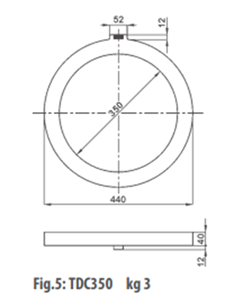
| TDC350 | Figure 5. | 3,0 | ||||||||||
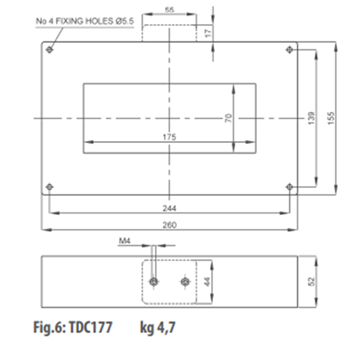
| TDC177 | Figure 6. | 4,7 | ||||||||||
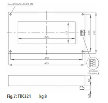
| TDC321 | Figure 7. | 8,0 | ||||||||||
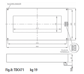
| TDC471 | Figure 8. | 19,0 | ||||||||||
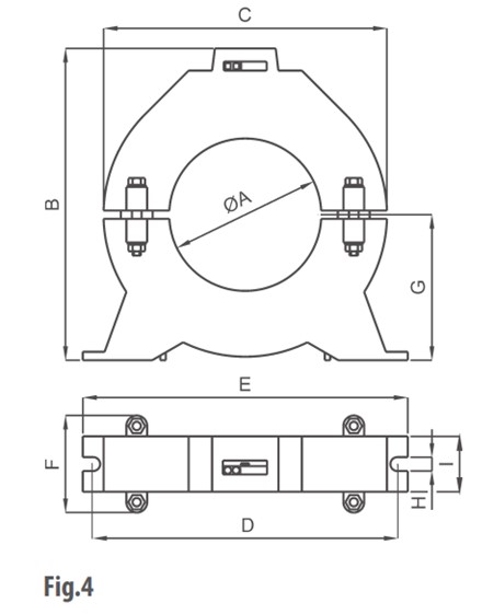
| TDA060 | Split | Fig. 4 | 60 | 121 | 130 | 110 | 120 | - | 56 | 6,5 | 28 | 0,8 |
| TDA110 | Fig. 4 | 110 | 225 | 205 | 220 | 235 | 70 | 105 | 6,5 | 40 | 1,3 | |
| TDA160 | Fig. 4 | 160 | 275 | 255 | 265 | 275 | 75 | 130 | 8,5 | 45 | 1,3 | |
| TDA210 | Fig. 4 | 210 | 325 | 305 | 310 | 325 | 75 | 155 | 8,5 | 45 | 2,4 | |
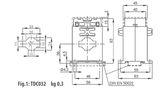
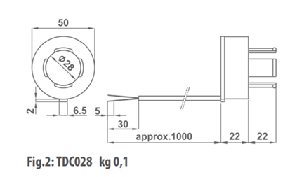
| Figure 1: TDC032 - Dimensions | Figure 2: TDC028 - Dimensions |
|---|---|
 |
 |
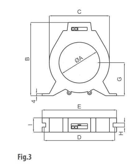
| Figure 3: TDC - Dimensions | Figure 4: TDA - Dimensions |
 |
 |
| Figure 5: TDC350 - Dimensions | Figure 6: TDC177 - Dimensions |
 |
 |
| Figure 7: TDC321 - Dimensions | Figure 8: TDC471 - Dimensions |
 |
 |
Êtes-vous intéressé par ce produit? Avez-vous besoin d'informations supplémentaires ou d'une tarification individuelle?
Ajouter à la liste de souhaits
Vous devez être connecté
The TDC and TDA series are current transformers designed for use with [Type A-F Earth Leakage Relays].
They must be installed with all single- or three-phase network conductors (phases and neutral, if present) routed inside the core. The protective conductor (PE or PEN) (for TN-C systems) must be located outside the core. The connection between the transformer and the leakage current relay must be made using the shortest possible length of shielded cable (shield grounded at one end) and routed at a significant distance from power circuits to minimize coupling interference and voltage drops on the resistances of the supply conductors.
| Parameter | Value |
|---|---|
| Self estinguishing (Thermoplastic material) | UL 90-V0 |
| Operating frequency | 47-63Hz |
| Insulation | 2,5kV 50Hz, 1 min. |
| Protection degree | IP20 |
| Continuous overload | 1000A |
| Thermal overload (1s) | 40kA |
| Operating temperature | 0…+50˚C U.R./R.H. < 90% n.c. |
| Storage temperature | -20…+70˚C |
| Connections | Screw, max 1,6mm2 |
| Code | Core | Figure | A | B | C | D | E | F | G | H | I | kg |
|---|---|---|---|---|---|---|---|---|---|---|---|---|
| TDC032 | Closed | Figure 1. | 0,3 | |||||||||
| TDC028 | Figure 2. | 0,1 | ||||||||||
| TDC035 | Fig. 3 | 35 | 102 | 73 | 92 | 100 | - | 40 | 6 | 28 | 0,2 | |
| TDC060 | Fig. 3 | 60 | 135 | 98 | 116 | 125 | - | 55 | 6 | 28 | 0,2 | |
| TDC080 | Fig. 3 | 80 | 154 | 118 | 136 | 146 | - | 65 | 6 | 38 | 0,4 | |
| TDC110 | Fig. 3 | 110 | 180 | 148 | 166 | 178 | - | 85 | 6 | 28 | 0,5 | |
| TDC160 | Fig. 3 | 160 | 283 | 255 | 265 | 275 | - | 130 | 8,5 | 45 | 1,2 | |
| TDC210 | Fig. 3 | 210 | 335 | 305 | 310 | 325 | - | 155 | 8,5 | 45 | 2,4 | |
| TDC350 | Figure 5. | 3,0 | ||||||||||
| TDC177 | Figure 6. | 4,7 | ||||||||||
| TDC321 | Figure 7. | 8,0 | ||||||||||
| TDC471 | Figure 8. | 19,0 | ||||||||||
| TDA060 | Split | Fig. 4 | 60 | 121 | 130 | 110 | 120 | - | 56 | 6,5 | 28 | 0,8 |
| TDA110 | Fig. 4 | 110 | 225 | 205 | 220 | 235 | 70 | 105 | 6,5 | 40 | 1,3 | |
| TDA160 | Fig. 4 | 160 | 275 | 255 | 265 | 275 | 75 | 130 | 8,5 | 45 | 1,3 | |
| TDA210 | Fig. 4 | 210 | 325 | 305 | 310 | 325 | 75 | 155 | 8,5 | 45 | 2,4 | |
| Figure 1: TDC032 - Dimensions | Figure 2: TDC028 - Dimensions |
|---|---|
 |
 |
| Figure 3: TDC - Dimensions | Figure 4: TDA - Dimensions |
 |
 |
| Figure 5: TDC350 - Dimensions | Figure 6: TDC177 - Dimensions |
 |
 |
| Figure 7: TDC321 - Dimensions | Figure 8: TDC471 - Dimensions |
 |
 |
Votre avis ne peut pas être envoyé
Signaler le commentaire
Signalement envoyé
Votre signalement ne peut pas être envoyé
Donnez votre avis
Avis envoyé
Votre avis ne peut être envoyé
