shopping_cart
Chariot
0,00 PLN
0
Cache
Vous devez être connecté
-
-
-
Category
-
Semi-conducteurs
- La diode
- Les thyristors
- Modules de puissance isolés
- Ponts redresseurs
-
Transistors
- Transistors | GeneSiC
- Modules MOSFET SiC | Mitsubishi
- Modules MOSFET SiC | STARPOWER
- Modules MOSFET SiC ABB
- Modules IGBT | MITSUBISHI
- Modules de transistors | MITSUBISHI
- Modules MOSFET | MITSUBISHI
- Modules de transistors | ABB
- Modules IGBT | POWEREX
- Modules IGBT | INFINEON (EUPEC)
- Composants semiconducteurs en carbure de silicium
- Przejdź do podkategorii
- Circuits de commande
- Blocs de puissance
- Przejdź do podkategorii
- Transducteurs électriques
-
Composants passifs (condensateurs, résistances, fusibles, filtres)
- Résistances
-
Fusibles
- Fusibles miniatures pour c.imp. série ABC et AGC
- Fusible rapides tubulaires
- Cartouches de courbe GL/GG et AM
- Cartouches ultrarapides
- Fusibles à action rapide (norme britannique et américaine)
- Fusibles à action rapide (norme européenne)
- Fusibles de traction
- Cartouche de haute tension
- Przejdź do podkategorii
-
Condensateurs
- Condensateurs pour moteurs
- Condensateurs électrolitiques
- Condensateurs de type snubbers
- Condensateurs de puissance
- Condensateurs pour circuits continus
- Condensateurs de compensation de puissance
- Condensateurs de haute tension
- Condensateurs pour chauffage par induction
- Condensateurs pour impulsions
- Condensateurs DC LINK
- Condensateurs pour circuits AC/DC
- Przejdź do podkategorii
- Filtres anti-interférences
- Supercondensateurs
- Protection contre les surtensions
- Filtres de détection des émissions TEMPEST
- Parafoudre
- Przejdź do podkategorii
-
Relais et contacteurs
- Théorie relais et contacteurs
- Relais statiques triphasés
- Relais statiques CC
- Régulateurs, circuits de commande et accessoires
- Démarrages progressifs et contacteurs inverseurs
- Relais electromécaniques
- Contacteurs
- Commutateurs rotatifs
-
Relais statiques monophasés
- Relais semi-conducteurs AC monophasés, série 1 | D2425 | D2450
- Relais à semi-conducteurs CA monophasés, séries CWA et CWD
- Relais à semi-conducteurs CA monophasés des séries CMRA et CMRD
- Relais à semi-conducteurs CA monophasés, série PS
- Relais semi-conducteurs AC double et quadruple, série D24 D, TD24 Q, H12D48 D
- Relais statiques monophasés, série GN
- Relais à semi-conducteurs CA monophasés, série CKR
- Relais AC monophasés SÉRIES ERDA ET ERAA pour rail DIN
- Relais CA monophasés pour courant 150A
- Relais à semi-conducteurs doubles intégrés à un dissipateur thermique pour un rail DIN
- Przejdź do podkategorii
- Relais statiques monophasé pour c.imp.
- Relais d'interface
- Przejdź do podkategorii
- Composants inductifs
- Radiateurs, varistances, protections thermiques
- Ventilateurs
- Climatiseurs et accessoires d'armoires électriques
-
Batteries, chargeurs, blocs d'alimentation tampon et onduleurs
- Batteries et Chargeurs - théorie
- Batteries Li-ion et non-standards. Systèmes de gestion des batteries (BMS)
- Batteries
- Chargeurs de batteries et accessoires
- Alimentation de secours UPS et alimentation tampon
- Convertisseurs de tension et accessoires pour photovoltaïque
- Stockage d'Energie
- Réservoirs de carburant
- Batteries lithium-ion
- Przejdź do podkategorii
-
Automatique industrielle
- Élévateurs Spiralift
- Pièces pour drones Futaba
- Interrupteurs de fin de course, micro-rupteurs
- Capteurs et convertisseurs
- Pyromètres
- Compteurs, Relais temporisés, Indicateurs de tableau
- Appareils industriels de protection
- Signalisation lumineuse et sonore
- Caméra thermique
- Afficheurs à LED
- Boutons et commutateurs
- Przejdź do podkategorii
-
Câbles et chemins de câbles
- Fils
- Passe-câbles et coupleurs
- Fils de Litz
-
Câbles pour les applications spéciales
- Câbles de compensation
- Câbles pour thermocouple
- Câble pour sondes Pt
- Câbles multi-brins temp. -60C do +1400C
- SILICOUL câbles moyenne tension
- Câbles d'allumage
- Câbles chauffants
- Câble mono-brin temp. -60C do +450C
- Câbles pour chemins de fer
- Câbles chauffants Ex
- Câbles pour l'industrie de la défense
- Przejdź do podkategorii
- Gaines
-
Tresses
- Tresses plates
- Tresses rondes
- Tresses très souples - plates
- Tresses très souples - rondes
- Tresses cuivre cylindriques
- Tresses cuivre cylindriques et protection
- Bandes de mise à la terre souples
- Tresses isolantes en PVC - temp. 85°C
- Tresses plates en aluminium
- Kit de liaison - tresses et gaines
- Tresses en acier
- Przejdź do podkategorii
- Equipement pour la traction
- Cosses
- Barres flexible isolées
- Barre flexibles multicouches
- Systèmes de traçage des câbles
- Przejdź do podkategorii
- Contactez-nous !
-
Semi-conducteurs
-
-


Type de connecteur PowerLock
Information
Les produits marqués «En commande» dans la colonne «Quantité disponible» ne sont généralement pas en stock. Ces produits sont disponibles à l'achat, cependant, en raison de leur clientèle limitée, ils ont généralement des quantités minimales plus élevées. DACPOL propose des produits qui ne sont pas en stock pour les raisons suivantes: DACPOL a actuellement un grand nombre de composants électroniques en stock et ajoute de nouveaux produits chaque jour, cependant, des dizaines de milliers de composants supplémentaires et leurs différentes variantes sont disponibles chez nos fournisseurs. Même s'il n'est pas raisonnable d'avoir tous ces produits en stock en raison des ventes limitées, nous pensons qu'il est dans le meilleur intérêt de nos clients de les rendre disponibles. Notre objectif est d'informer les clients sur le nombre maximum de produits disponibles et de leur permettre de prendre des décisions en fonction des spécifications, des prix, de la disponibilité, des minimums requis et de nos conseils techniques. Veuillez noter que la sélection de la case à cocher «En stock» peut limiter l'affichage aux seuls produits disponibles à la livraison directement en rayon.
| Image | Voir le produit | Fabricant no | ||||
|---|---|---|---|---|---|---|
| picture_as_pdf |
|
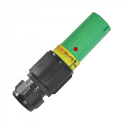
Phase 3 Connectors ltd | Connecteurs POWERLOCK | VOIR | -- | En commande |
| picture_as_pdf |

|
Phase 3 Connectors ltd | Boîtier de distribution Powersafe 2U | VOIR | PS2U | En commande |
| picture_as_pdf |
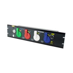
|
Phase 3 Connectors ltd | Boîtier de distribution Powersafe 4U | VOIR | PS4U | En commande |
Résultats par page:
Articles Similaires
")
")
