shopping_cart
Karte
0,00 PLN
0
Zwischenablage
Sie müssen eingeloggt sein
-
-
-
Category
-
Halbleiter
- Dioden
- Thyristoren
- Elektroisolierte Module
- Brückengleichrichter
-
Transistoren
- Transistoren | GeneSiC
- SiC-MOSFET-Module | Mitsubishi
- SiC-MOSFET-Module | STARPOWER
- ABB SiC-MOSFET-Module
- IGBT-Module | MITSUBISHI
- Transistormodule | MITSUBISHI
- MOSFET-Module von MITSUBISHI
- Transistormodule | ABB
- IGBT-Module | POWEREX
- IGBT-Module | INFINEON (EUPEC)
- Halbleiterkomponente aus Siziliumkarbid
- Przejdź do podkategorii
- Treiber
- Leistungsblöcke
- Przejdź do podkategorii
- Strom- und Spannungswandler von LEM
-
Passive Elemente (Kondensatoren, Widerstände, Sicherungen, Filter)
- Widerstände
-
Sicherungen
- Miniatursicherungen für elektronische Schaltungen der Serien ABC und AGC
- Schnelle Röhrensicherungen
- Zeitverzögerungssicherungen mit GL / GG- und AM-Eigenschaften
- Ultraschnelle Sicherungseinsätze
- Britische und amerikanische schnelle Sicherungen
- Schnelle europäische Sicherungen
- Traktionssicherungen
- Hochspannungs-Sicherungseinsätze
- Przejdź do podkategorii
-
Kondensatoren
- Kondensatoren für Motoren
- Elektrolytkondensator
- Island Filmkondensatoren
- Leistungskondensatoren
- Kondensatoren für Gleichstromkreise
- Kondensatoren zur Leistungskompensation
- Hochspannungskondensatoren
- Induktionsheizkondensatoren
- Impulskondensatoren
- DC LINK-Kondensatoren
- Kondensatoren für AC / DC-Schaltungen
- Przejdź do podkategorii
- Entstörungsfilter
- Superkondensatoren
- Überspannungsschutz
- TEMPEST-Strahlungserkennungsfilter
- Überspannungsableiter
- Przejdź do podkategorii
-
Relais und Schütze
- Theorie der Relais und Schütze
- Dreiphasen-Halbleiterrelais AC
- Halbleiterrelais DC
- Regler, Steuerungen und Zubehör
- Sanftstarter und Schaltschütze
- Elektromechanische Relais
- Schütze
- Drehschalter
-
Einphasen-Halbleiterrelais AC
- Einphasen-Wechselstrom-Halbleiterrelais, Serie 1 | D2425 | D2450
- Einphasige AC-Halbleiterrelais der Serien CWA und CWD
- Einphasen-Wechselstrom-Halbleiterrelais der Serien CMRA und CMRD
- Einphasen-Wechselstrom-Halbleiterrelais, PS-Serie
- Doppel- und Vierfach-Wechselstrom-Halbleiterrelais, Serie D24 D, TD24 Q, H12D48 D.
- 1-phasige Festkörperrelais, gn-Serie
- Einphasige Wechselstrom-Halbleiterrelais, Serie ckr
- Einphasen-Wechselstromrelais der ERDA- UND ERAA-SERIE für die DIN-Schiene
- Einphasige Wechselstromrelais für 150A Strom
- Doppelte Halbleiterrelais mit integriertem Kühlkörper für eine DIN-Schiene
- Przejdź do podkategorii
- Einphasen-Halbleiterrelais AC für Leiterplatten
- Interface-Relais
- Przejdź do podkategorii
- Induktive Komponente
- Radiatoren, Varistoren, Thermoschütze
- Ventilatoren
- Klimaanlagen, Ausrüstung für Schaltschränke, Industriekühler
-
Batterien, Ladegeräte, Pufferstromversorgungen und Wechselrichter
- Batterien, Ladegeräte - theoretische Beschreibung
- Lithium-Ionen-Batterien. Kundenspezifische Batterien. Batteriemanagementsystem (BMS)
- Batterien
- Ladegeräte und Zubehör
- USV-Notstromversorgung und Pufferstromversorgung
- Konverter und Zubehör für die Photovoltaik
- Energiespeicher
- Brennstoffzellen
- Lithium-Ionen-Batterien
- Przejdź do podkategorii
-
Automation
- Spiralift Hebebühnen
- Futaba Drohnenteile
- Grenzschalter, Microschalter
- Sensoren, Wandler
-
Pyrometer
- Infrarot-Temperatursensor, kabellos, wasserdicht, IR-TE-Serie
- Infrarot-Temperatursensor, kabellos, IR-TA-Serie
- Infrarot-Temperatursensor, kabellos, IR-H-Serie
- Ein schnelles stationäres Pyrometer in einem sehr kleinen IR-BA-Gehäuse
- Lichtleiter-Temperatursensoren, IR-FA-Serie
- Das stationäre Pyrometer der IR-BZ-Serie
- Przejdź do podkategorii
- Zähler, Zeitrelais, Einbaumessgeräte
- Industrielle Schutzausrüstung
- Licht- und Signalentechnik
- Infrarot-Kamera
- LED-Anzeigen
- Taster, Schalter und Zubehör
- Przejdź do podkategorii
-
Adern, Litzen, Schutzhüllen, Flexible Verbingungen
- Drähte
- Kabeleinführungen und Kupplungen
- Litzen
- Kabel für spezielle Anwendungen
- Schläuche
-
Geflochtene Kabel
- Zöpfe flach
- Zöpfen Runde
- Sehr flexible Geflecht - flach
- Sehr flexible Geflecht - Rund
- Kupfergeflecht zylindrischen
- Kupfergeflechtschirm und zylindrischer
- Flexible Massebänder
- PVC-isolierte Kupferlitzen - Temperatur 85 ° C
- Flach geflochtene Aluminium
- Connection Kit - Zöpfe und Röhren
- Stahlgeflechte
- Przejdź do podkategorii
- Leitungen und Sonstiges für Traktion
- Crimpverbinder
- Flexible isolierte Kupferschienen
- Mehrschichte flexible Kupferschienen
- Kabelrohre, Kabelkanäle und Kabelführung
- Przejdź do podkategorii
- Zobacz wszystkie kategorie
-
Halbleiter
-
-


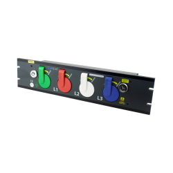
Powerlock-Anschlüsse
Information
Produkte, die in der Spalte "Verfügbare Menge" mit "Auf Bestellung" gekennzeichnet sind, sind normalerweise nicht auf Lager. Solche Produkte sind käuflich zu erwerben, haben jedoch aufgrund ihrer begrenzten Kundenbasis in der Regel höhere Mindestmengen. DACPOL bietet Produkte an, die aus folgenden Gründen nicht auf Lager sind: DACPOL hat derzeit eine große Menge elektronischer Komponenten auf Lager und fügt täglich neue Produkte hinzu. Unsere Lieferanten verfügen jedoch über Zehntausende zusätzlicher Komponenten und deren verschiedene Varianten. Obwohl es aufgrund des begrenzten Umsatzes nicht zumutbar ist, alle diese Produkte auf Lager zu haben, glauben wir, dass es im besten Interesse unserer Kunden ist, sie zur Verfügung zu stellen. Unser Ziel ist es, Kunden über die maximale Anzahl verfügbarer Produkte zu informieren und ihnen zu ermöglichen, Entscheidungen auf der Grundlage von Spezifikationen, Preisen, Verfügbarkeit, erforderlichen Mindestanforderungen und unserer technischen Beratung zu treffen. Bitte beachten Sie, dass das Aktivieren des Kontrollkästchens "Auf Lager" die Anzeige möglicherweise auf Produkte beschränkt, die direkt aus dem Regal geliefert werden können.
| Bild | Produkt anzeigen | Hersteller-Nr | ||||
|---|---|---|---|---|---|---|
| picture_as_pdf |

|
Phase 3 Connectors ltd | PowerLock-Anschlüsse | SEHEN SIE ES | -- | Verfügbare Menge |
| picture_as_pdf |
|
Phase 3 Connectors ltd | Powersafe 2U Verteilerkasten | SEHEN SIE ES | PS2U | Verfügbare Menge |
| picture_as_pdf |

|
Phase 3 Connectors ltd | Powersafe 4U Verteilerkasten | SEHEN SIE ES | PS4U | Verfügbare Menge |
Ergebnisse pro Seite:
Zusammenhängende Posts
 Steckverbindern")
-Steckverbinder sicher anschließt")
