-
-
-
Category
-
Semiconductors
- Diodes
- Thyristors
-
Electro-insulated Modules
- Electro-insulated Modules | VISHAY (IR)
- Electro-insulated Modules | INFINEON (EUPEC)
- Electro-insulated Modules | Semikron
- Electro-insulated Modules | POWEREX
- Electro-insulated Modules | IXYS
- Electro-insulated Modules | POSEICO
- Electro-insulated Modules | ABB
- Electro-insulated Modules | TECHSEM
- Go to the subcategory
- Bridge Rectifiers
-
Transistors
- Transistors | GeneSiC
- SiC MOSFET Modules | Mitsubishi
- SiC MOSFET Modules | STARPOWER
- Module SiC MOSFET ABB’s
- IGBT Modules | MITSUBISHI
- Transistor Modules | MITSUBISHI
- MOSFET Modules | MITSUBISHI
- Transistor Modules | ABB
- IGBT Modules | POWEREX
- IGBT Modules | INFINEON (EUPEC)
- Silicon Carbide (SiC) semiconductor elements
- Go to the subcategory
- Gate Drivers
- Power Blocks
- Go to the subcategory
- Electrical Transducers
-
Passive components (capacitors, resistors, fuses, filters)
- Resistors
-
Fuses
- Miniature Fuses for electronic circuits - ABC & AGC Series
- Tubular Fast-acting Fuses
- Time-delay Fuse Links with GL/GG & AM characteristics
- Ultrafast Fuse Links
- Fast-acting Fuses (British & American standard)
- Fast-acting Fuses (European standard)
- Traction Fuses
- High-voltage Fuse Links
- Go to the subcategory
- Capacitors
- EMI Filters
- Supercapacitors
- Power surge protection
- TEMPEST emission revealing filters
- Surge arrester
- Go to the subcategory
-
Relays and Contactors
- Relays and Contactors - Theory
- 3-Phase AC Semiconductor Relays
- DC Semiconductor Relays
- Controllers, Control Systems and Accessories
- Soft Starters and Reversible Relays
- Electromechanical Relays
- Contactors
- Rotary Switches
-
Single-Phase AC Semiconductor Relays
- AC ONE PHASE RELAYS 1 series| D2425 | D2450
- One phase semiconductor AC relays CWA and CWD series
- One phase semiconductor AC relays CMRA and CMRD series
- One phase semiconductor AC relays - PS series
- Double and quadruple semiconductor AC relays - D24 D, TD24 Q, H12D48 D series
- One phase semiconductor relays - gn series
- Ckr series single phase solid state relays
- One phase AC semiconductor relays for DIN bus - ERDA I ERAA series
- 150A AC single phase relays
- Rail Mountable Solid State Relays With Integrated Heat Sink - ENDA, ERDA1 / ERAA1 series
- Go to the subcategory
- Single-Phase AC Semiconductor Relays for PCBs
- Interface Relays
- Go to the subcategory
- Cores and Other Inductive Components
- Heatsinks, Varistors, Thermal Protection
- Fans
- Air Conditioning, Accessories for Electrical Cabinets, Coolers
-
Batteries, Chargers, Buffer Power Supplies and Inverters
- Batteries, Chargers - Theoretical Description
- Modular Li-ion Battery Building Blocks, Custom Batteries, BMS
- Batteries
- Battery Chargers and Accessories
- Uninterruptible Power Supply and Buffer Power Supplies
- Inverters and Photovoltaic Equipments
- Energy storage
- Fuel cells
- Lithium-ion batteries
- Go to the subcategory
-
Automatics
- Spiralift Lifts
- Futaba Drone Parts
- Limit Switches, Microswitches
- Sensors, Transducers
-
Infrared Thermometers (Pyrometers)
- IR-TE Series - Water-proof Palm-sized Radiation Thermometer
- IR-TA Series - Handheld Type Radiation Thermometer
- IR-H Series - Handheld Type Radiation Thermometer
- IR-BA Series - High-speed Compact Radiation Thermometer
- IR-FA Series - Fiber Optic Radiation Thermometer
- IR-BZ Series - Compact Infrared Thermometers
- Go to the subcategory
- Counters, Time Relays, Panel Meters
- Industrial Protection Devices
- Light and Sound Signalling
- Thermographic Camera
- LED Displays
- Control Equipments
- Go to the subcategory
-
Cables, Litz wires, Conduits, Flexible connections
- Wires
- Cable feedthroughs and couplers
- Litz wires
-
Cables for extreme applications
- Extension and Compensation cables
- Thermocouple cables
- Connection cables for PT sensors
- Multi-conductor wires (temp. -60C to +1400C)
- Medium voltage cables
- Ignition wires
- Heating cables
- Single conductor cables (temp. -60C to +450C)
- Railway cables
- Heating cables Ex
- Cables for the defense industry
- Go to the subcategory
- Sleevings
-
Braids
- Flat Braids
- Round Braids
- Very Flexible Flat Braids
- Very Flexible Round Braids
- Cylindrical Cooper Braids
- Cylindrical Cooper Braids and Sleevings
- Flexible Earthing Connections
- PCV Insulated Copper Braids (temp. up to 85C)
- Flat Aluminium Braids
- Junction Set - Braids and Tubes
- Steel Braids
- Go to the subcategory
- Traction Equipment
- Cable Terminals
- Flexible Insulated Busbars
- Flexible Multilayer Busbars
- Cable Duct Systems
- Go to the subcategory
- View all categories
-
Semiconductors
-
-


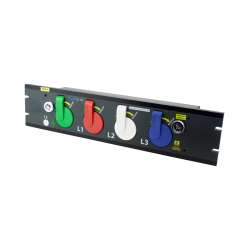
Power Connectors Powersafe
Information
Products that are marked "On Order" in the "Available Quantity" column are usually not in stock. Such products are available for purchase, however, due to their limited customer base, they usually have higher minimum quantities. DACPOL offers products that are not in stock for the following reasons: DACPOL currently has a large number of electronic components in stock and adds new products every day, however, tens of thousands of additional components and their various variants are available from our suppliers. Even though it is unreasonable to have all these products in stock due to the limited sales, we believe that it is in the best interest of our customers to make them available. Our goal is to inform customers about the maximum number of products available and enable them to make decisions based on specifications, prices, availability, required minimums and our technical advice. Please note that selecting the "In Stock" checkbox may limit the display to only products available for delivery straight from the shelf.
| Image | View the product | No. Manufacturer | ||||
|---|---|---|---|---|---|---|
| picture_as_pdf |

|
Phase 3 Connectors ltd | Powersafe - PowerLock connectors | SEE IT | -- | On Order |
| picture_as_pdf |
|
Phase 3 Connectors ltd | Powersafe 2U distribution box | SEE IT | PS2U | On Order |
| picture_as_pdf |

|
Phase 3 Connectors ltd | Powersafe 4U distribution box | SEE IT | PS4U | On Order |
Results per page:
Related posts
 Connectors")
 Connectors")
