The introduction of the GKS product marks a significant new product class for Honeywell. Honeywell’s switching expertise has been applied to a cost-effective, trapped key safety interlock switch. This product allows OEMs to hold a door or gate closed while a hazard still exists. This is particularly important where there is moment
um in the machine. In other words, when the machine is signaled to stop, the momentum in the machine can mean that parts of the machine are still moving and pose an injury risk if the access gate or door is not held closed. Global approvals and standards are important to Honeywell’s customers; therefor e, the GKS product conform to
the requirements of IEC60947-5-1 and carries cULus, CE and CCC approvals
FEATURES:
• Global approvals (CE, cULus, CE, and CCC)
• Glass-filled polyester body
• Power-to-lock and power-to-unlock schemes for key trap
• Flexible switching arrangement
• 24 Vdc, 110 Vac, and 230 Vac coil voltages
• Over-ride mechanism in cover
• Head may be rotated into 4 different positions
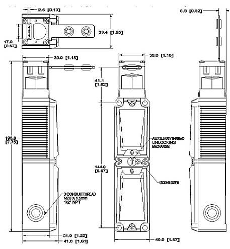
• Three conduit openings (knock-out style)
• Switch position provides status .
Benefits
• Product may be applied to most applications worldwide
• Tough, cost-effective, double-insulated enclosure
• Choice of key trapping methodology
• Four contacts that can be arranged in any configuration
• Multiple voltages provide for every geography
• Has a method to open door (in case of power loss, etc.)
• One part number may be used for multiple applications
• Flexible wiring options
• Can diagnose status of gate/door (gate/door closed and locked, gate/door closed and unlocked, gate/door open)
Caution
There will be minimum volume requirements for unreleased
options.
POTENTIAL APPLICATIONS
• Woodworking machinery
• Printing/paper finishing equipment
• Plastic molding equipment
• Packaging machinery
• Bailing
• Pumping equipment
• Semiconductor manufacturing equipment
• Packaging wrapping
• Specialty equipment
• Machine tool
• Robot cell
Low Voltage Directive 73/23/EEC, as amended by directive 93/68/EEC.Machinery Directive 98/37/EEC only as the directives relate to the components being used in a safety function.
The part number tree is provided to demons trate the potential combinations of components. Actual availability of individual product combinations will depend on the popularity of that type. Please check with your local distributor or Honeywell representative for the available types in your region
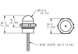
The built-in LED is suitable for direct installation in the M20 x1.5/0.5 in NPT thread, one of the three cable entries in the
GKS safety switch. The built-in LED can indicate to the user whether the solenoid is unlocked/locked or whether the door is open/closed. The switching element can be wired individually.