|
Electrical data:
|
|
Nominal voltage(UR):
|
250V 50/60HZ
|
|
Nominal current (IN):
|
at ambient temperature 40°C
|
|
Leakage current(IL ):
|
maximum value at 220V, 50Hz
|
|
Voltage test (2s):
|
line - ground3000 VDC or 1800 VAC
|
| |
line - line 1700 VDC
|
|
Climatic category
|
HPF (25/85/21)
|
|
Temperature range:
|
-25°C - 85°C
|
| Type |
IN
[A] |
L
[mH] |
Cx
[µF] |
Cy
[pF] |
IL
[mA] |
R
[MΩ] |
Scheme |
Casing |
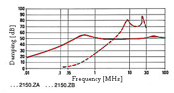
| F.AI.DB.2150.ZA |
1,5 |
2 x 10 |
0,015 |
2 x 2200 |
2 x 0,2 |
|
A |
A |
| F.AI.DB.2150.ZB |
1 |
2 x 10 |
0,015 |
2 x 2200 |
2 x 0,2 |
|
A |
A |
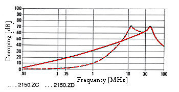
| F.AI.DB.2150.ZC |
3 |
2 x 2 |
0,015 |
2 x 2200 |
2 x 0,2 |
|
A |
A |
| F.AI.DB.2150.ZD |
6,5 |
2 x 10 |
0,015 |
2 x 2200 |
2 x 0,2 |
|
A |
A |
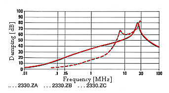
| F.AI.D-.2330.ZA |
10 |
2 x 0,5 |
0,033 |
2 x 2200 |
2 x 0,2 |
1 |
B |
B |
| F.AI.D-.2330.ZB |
20 |
2 x 0,5 |
0,033 |
2 x 2200 |
2 x 0,2 |
1 |
B |
B |
| F.AI.D-.2330.ZC |
30 |
2 x 0,6 |
0,033 |
2 x 2200 |
2 x 0,2 |
1 |
B |
D |
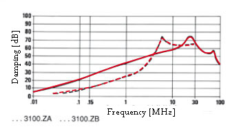
| F.AI.D-.3100.ZA |
5 |
2 x 1 |
0,1 |
2 x 3200 |
2 x 0,29 |
1 |
B |
B |
| F.AI.D-.3100.ZB |
5 |
2 x 17 |
0,1 |
2 x 3200 |
2 x 0,29 |
1 |
B |
B |
Caution
Terminals: B - connectors, D - wire, I - screw
Casing drawings at the end of the section
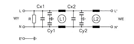
Scheme A
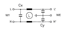
Scheme B
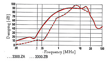
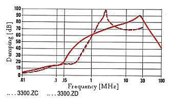
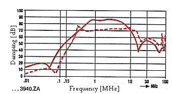
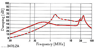
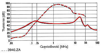
Characteristics– attenuation
..................symmetrical(line - line)
_________asymmetrical (line - ground)
| Type |
IN
[A] |
L1
[mH] |
I2
[mH] |
Cx1
[µF] |
Cx2
[µF] |
Cx3
[µF] |
Cy1
[pF] |
Cy2
[pF] |
IL
[mA] |
R
[MΩ] |
Scheme |
Casing |
| FAK.D-.3300.ZA |
3 |
2 x 2 |
2 x 2 |
0,15 |
0,15 |
|
2 x 2200 |
|
2 x 0,2 |
1 |
E |
C1 |
| FAK.D-.3300.ZB |
6 |
2 x 1 |
2 x 1 |
0,15 |
0,15 |
|
2 x 2200 |
|
2 x 0,2 |
1 |
E |
C1 |
| FAK.D-.3300.ZC |
10 |
2 x 0,5 |
2 x 0,5 |
0,15 |
0,15 |
|
2 x 2200 |
|
2 x 0,2 |
1 |
E |
C2 |
| FAK.D-.3300.ZD |
20 |
2 x 0,5 |
2 x 0,5 |
0,15 |
0,15 |
|
2 x 2200 |
|
2 x 0,2 |
1 |
E |
D |
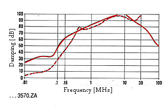
| FAK.D-.3570.ZA |
2,5 |
2 x 1 |
2 x 25 |
|
0,47 |
0,1 |
2 x 3300 |
2 x 3300 |
2 x 0,6 |
0,68 |
E |
D |
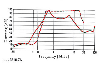
| FAK.D-.3810.ZA |
10 |
2 x 2,3 |
2 x 2,3 |
0,27 |
0,27 |
0,27 |
2 x 5500 |
2 x 1000 |
2 x 0,6 |
0,38 |
E |
D |
| FAK.D-.3940.ZA |
3 |
2 x 4,7 |
2 x 4,7 |
0,47 |
0,47 |
|
2 x 4700 |
|
2 x 0,5 |
0,24 |
F |
C2 |
Caution
Terminals: B - connectors, D - wire, I - screw
Casing drawings at the end of the section
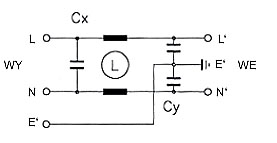
Scheme E
Scheme F
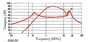
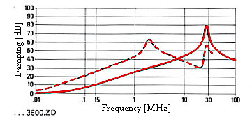
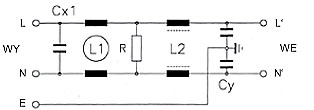
Characteristics– attenuation
..................symmetrical(line - line)
_________asymmetrical (line - ground)
| Type |
IN
[A] |
L
[mH] |
Cx1
[µF] |
Cx2
[µF] |
Cy
[pF] |
IL
[mA] |
R
[MΩ] |
Scheme |
Casing |
| F.AM.D-.3200.ZA |
1 |
2 x 40 |
0,1 |
0,1 |
2 x 4700 |
2 x 0,43 |
0,68 |
C |
B |
| F.AM.D-.3200.ZB |
5 |
2 x 1 |
0,1 |
0,1 |
2 x 3200 |
2 x 0,29 |
0,68 |
C |
B |
| F.AM.D-.3200.ZC |
10 |
2 x 0,5 |
0,1 |
0,1 |
2 x 2200 |
2 x 0,2 |
0,68 |
c |
B |
| F.AM.D-.3200.ZD |
20 |
2 x 0,5 |
0,1 |
0,1 |
2 x 2200 |
2 x 0,2 |
0,68 |
c |
C2 |
| F.AM.D-.3200.ZE |
30 |
2 x 0,6 |
0,1 |
0,1 |
2 x 2200 |
2 x 0,2 |
0,68 |
c |
D |
| F.AM.D-.3440.ZA |
10 |
2 x 1 |
0,22 |
0,22 |
2 x 4700 |
2 x 0,43 |
0,47 |
D |
B |
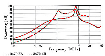
| F.AM.D-.3470.ZA |
6,5 |
2 x 4 |
|
0,47 |
2 x 1000 |
2 x 0,09 |
0,68 |
C |
C2 |
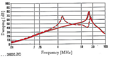
| F.AM.D-.3600.ZC |
16 |
2 x 1 |
|
0,6 |
2 x 2500 |
2 x 0,23 |
0,47 |
C |
C2 |
| F.AM.D-.3600.ZD |
22 |
2 x 0,2 |
|
0,6 |
2 x 2500 |
2 x 0,23 |
0,47 |
C |
C2 |
| F.AM.D-.3600.ZE |
20 |
2 x 1 |
|
0,6 |
2 x 4700 |
2 x 0,43 |
0,47 |
D |
C2 |
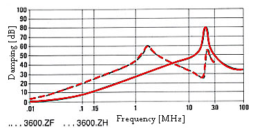
| F.AM.D-.3600.ZF |
40 |
2 x 0,23 |
|
0,6 |
2 x 4700 |
2 x 0,43 |
0,47 |
D |
C2 |
| F.AM.D-.3600.ZH |
30 |
2 x 0,23 |
|
0,6 |
2 x 4700 |
2 x 0,43 |
0,47 |
D |
C2 |
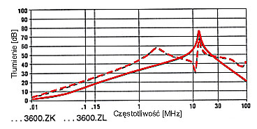
| F.AM.D-.3600.ZK |
25 |
2 x 0,5 |
0,6 |
|
2 x 4700 |
2 x 0,43 |
0,47 |
D |
C2 |
| F.AM.D-.3600.ZL |
25 |
2 x 0,5 |
0,6 |
|
2 x 22000 |
2 x 2 |
0,47 |
D |
C2 |
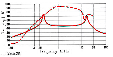
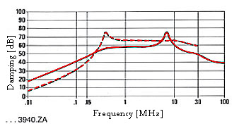
| F.AM.D-.3940.ZA |
4,5 |
2 x 20 |
0,47 |
0,47 |
2 x 10000 |
2 x 0,91 |
0,33 |
C |
C2 |
| F.AM.D-.3940.ZB |
3,3 |
2 x 13 |
0,47 |
0,47 |
2 x 6800 |
2 x 0,62 |
0,33 |
C |
C2 |
| F.AM.D-.4100.ZB |
16 |
2 x 0,5 |
|
1 |
2 x 2500 |
2 x 0,23 |
0,33 |
D |
C2 |
| F.AM.D-.4160.ZA |
25 |
2 x 0,5 |
1 |
0,68 |
2 x 22000 |
2 x 2 |
0,47 |
C |
C2 |
Caution
Terminals: B - connectors, D - wire, I - screw
Casing drawings at the end of the section
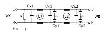
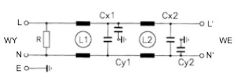
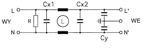
Scheme C
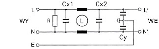
Scheme D
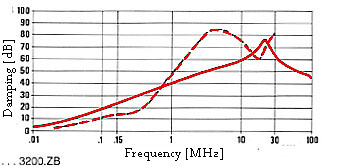
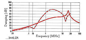
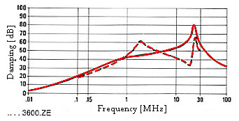
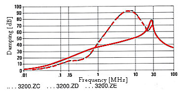
Characteristics– attenuation
..................symmetrical(line - line)
_________asymmetrical (line - ground)
| Type |
LN
[A] |
L1
[mH] |
l2
[mH] |
Cx1
[µF] |
Cx2
[µF] |
Cy1
[pF] |
Cy2
[pF] |
IL
[mA] |
R
[MΩ] |
Scheme |
Casing |
| F.AR.D-.3620.ZA |
1,5 |
2 x 7 |
2 x 7 |
0,47 |
0,15 |
|
2 x 2200 |
2 x 0,2 |
0,47 |
G |
C2 |
| F.AR.D-.3620.ZB |
2,5 |
2 x 12 |
2 x 2 |
0,47 |
0,15 |
|
2 x 2200 |
2 x 0,2 |
0,47 |
G |
C2 |
| F.AR.D-.3620.ZC |
5 |
2 x 7 |
2 x 7 |
0,47 |
0,15 |
|
2 x 2200 |
2 x 0,2 |
0,47 |
G |
C2 |
| F.AR.D-.3620.ZD |
8,5 |
2 x 10 |
2 x 3 |
0,47 |
0,15 |
|
2 x 2200 |
2 x 0,2 |
0,47 |
G |
D |
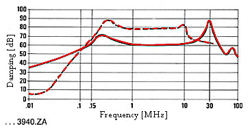
| F.AR.D-.3940.ZA |
0,5 |
2 x 40 |
2 x 40 |
0,47 |
0,47 |
2 x 3300 |
|
2 x 0,3 |
0,33 |
G |
Cl |
Caution
Terminals: B - connectors, D - wire, I - screw
Casing drawings at the end of the section
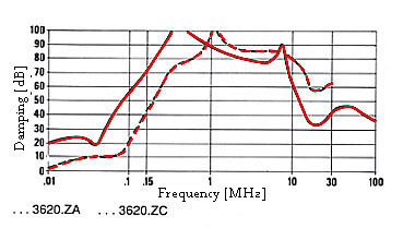
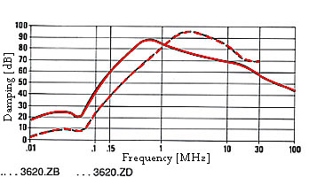
Characteristics– attenuation
..................symmetrical(line - line)
_________asymmetrical (line - ground)
| Type |
LN
[A] |
L1
[mH] |
l2
[mH] |
Cx
[µF] |
Cy
[pF] |
IL
[mA] |
R
[MΩ] |
Scheme |
Casing |
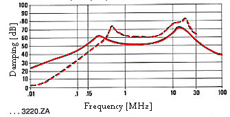
| F.AS.D-.3220.ZA |
1 |
22 |
0,3 |
0,22 |
2 x 4700 |
2 x 0,43 |
1 |
H |
B |
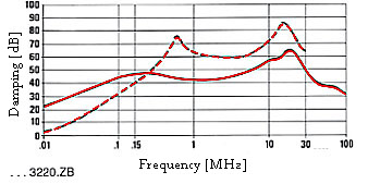
| F.AS.D-.3220.ZB |
2,5 |
16 |
0,3 |
0,22 |
2 x 4700 |
2 x 0,43 |
1 |
H |
C2 |
| F.AS.D-.3470.ZA |
6,5 |
4 |
0,05 |
0,47 |
2 x 22000 |
2 x 2 |
0,47 |
H |
D |
| F.AS.D-.3470.ZB |
10 |
4 |
0,05 |
0,47 |
2 x 22000 |
2 x 2 |
0,47 |
H |
D |
| F.AS.D-.3940.ZA |
4 |
8 |
0,05 |
0,94 |
2 x 22000 |
2 x 2 |
0,33 |
H |
C2 |
| F.AS.D-.3940.ZC |
10 |
4 |
0,05 |
2 x 0,47 |
2 x 22000 |
2 x 2 |
0,33 |
H |
C2 |
Caution
Terminals: D - wire,
Casing drawings at the end of the section
Characteristics– attenuation
..................symmetrical(line - line)
_________asymmetrical (line - ground)
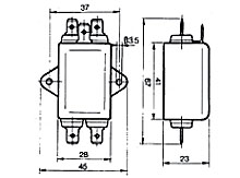
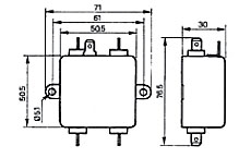
|
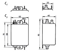
Casing A
|
Casing B
|
Casing C
|
|
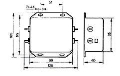
Casing D
|
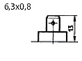
Terminal B
|
Terminal D
|
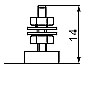
Terminal I
|