Applications
• Protection of people and machinery
• Monitoring of emergency stop applications
• Monitoring of safety gates
• Termination of braking operations through OFF-delay time
Function
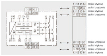
Device and function description
With the supply voltage applied to terminals A1/ A2 and the emergency stop circuitclosed, the control logic is activated with the reset button. This controls controls the K1 to K4 relays that become self-locking (when starting through reset buttonmonitoring after the response time). After this switch-on phase the 3 enablingcurrent paths are closed (terminals 13 / 14, 23 / 24 and 37 / 38).Three LEDs display the state of the relays K1/ K2, K3 / K4 and the supply voltage.If the emergency stop button is activated, the current supplies for the relays K1 to K4
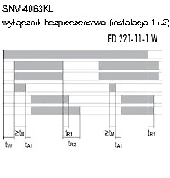
are interrupted. The undelayed enabling current paths (terminals 13 / 14, 23 / 24) areopened with release time tR1 while the off-delayed enabling current path (terminals37 / 38) is opened after the pre-set OFF-delay time tR2 The OFF-delay time can beadjusted infinitely in the range 0.15 to 3 s or 1.5 to 30 s. With a two-channel control
and cross-monitoring wiring of the sensor circuit, additional errors such as shunt faultor ground fault can be detected. An electronic fuse protects the device against damage. After the cause of the malfunction has been removed, the device isoperational again after approx. 3 s.
Reset button monitoring
The device can be started either with the falling edge or with the rising edge (terminalsS34 or S35). For emergency stop applications with manual start the button must be connected to terminals S33 / S34. The device is enabled only with the falling edge of the reset signal. For starting the reset button must be pressed and released. For safety gate applications in which an automatic start shall be performed it is necessary to jumper
terminals S33 /S35. The device will react at the rising edge of input S12 that isinternally connected to S33.
Synchrocheck
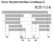
The use of safety limit switches for single-channel or two-channel circuits in safety gate applications depends on the required safety level. The device offersa two-channel control along with an optional synchrocheck of the limit switches.A synchronous time t=0.5 s requires limit switches positioned in a way thatchannel 1, terminals S11/ S12, closes before channel 2, terminals S21/ S22.If channel 2 closes before channel 1, the synchronous time is
tS=∞
.
Proper use
The devices are safety switching devices. They must only be used as components of
safety equipment on machines for the purpose of protecting people, material and
machines.
• The safety category according to EN 954-1 depends on the external circuitry, the
choice of control devices and their placement on the machine.
• The reset button used for manual start (S34) must not be actuated for more than 3 s.
The indicated times must be observed when the device is operated, otherwise the
device could lock. Locking can be released by properly opening the safety inputs.
• SNE expansion devices or external contactors with positively driven contacts can be
used to multiply the enabling current paths.
• The device and the contacts must be protected with max. 6 A utilization category gG
or through circuit breakers with trigger characteristic B or C.
• The devices are equipped with overload protection (for short circuit). After the cause
of the malfunction has been removed, the device is operational again after approx. 3 s.
• Control output S11/S33 is exclusively for connecting control devices as defined in the
operating instructions and not for connecting external field devices such as
lamps, relays or contactors.
• The emergency stop circuit must be closed before the reset button is activated.
• For connecting sensors with reed contacts or semiconductor outputs the peak
current must be considered (see “Technical data” – Control circuit).
• The devices must be installed in a control cabinet with a protection degree of at
least IP 54.
Connection scheme