Sensitivity Zone
The sensitivity zone for reflective sensors is the maximum distance from the sensor face of a measuring card (white cardboard measuring 20x20cm) approached along the light beam axis, at which the sensor's output circuit switches.
Range
The operating range for reflective optical sensors is the maximum distance from the sensor face of a reflective reflector, or for barrier-type sensors, the maximum distance between the transmitter and receiver of the barrier, which ensures correct operation of the sensors when the light rays are interrupted by an object within the range.
Hysteresis
The operation of optical sensors is characterized by the presence of switching hysteresis, which is the difference in the distance between the object and the sensor at which the sensor changes the state of the output circuit.
Coefficients Correction Factors
The amount of reflected light has a significant impact on the optical sensor's operating zone. It depends on the type of material the object is made of, its color, structure, and dimensions. Light surfaces, such as white paper, reflect more strongly than dark surfaces, such as black cardboard. Correction factors for various materials, taking into account the light reflection properties, are given below.
| Matte white paper 200g/m 2 |
1 |
| Shiny Metal |
1.2 - 1.6 |
| Black anodized aluminum |
1 .2 - 1.8 |
| White Styrofoam |
1 |
| Gray PVC |
0.5 |
| Glossy Black Cardboard |
0.3 |
| Matte Black Cardboard |
0.1 |
| Raw wood |
0.4 |
Output function
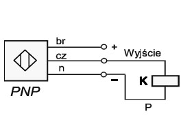
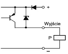
The sensors' binary contactless outputs enable direct interaction with relays and programmable logic controllers. Optical sensors with PNP switching transistors enable (NO) or disable (NC) the current in the load connected to the sensor output. In the PNP version, the sensors connect a positive potential to the sensor input.
Power supply
TO optical sensors are used in direct current automation systems (10...30V DC). The sensors are characterized by low current consumption from the power supply. The power supply largely determines the correct operation of optical sensors. Optical sensors can be powered by either stabilized or unstabilized DC voltage. When powered by unstabilized voltage, voltage ripple must not exceed 10%.
Residual Voltage
Residual voltage is defined as the voltage drop at the sensor's output when the output is activated.
Output Overload and Short Circuit Protection
Optical sensors powered by DC voltage have current protection that protects the sensors from damage due to short-term and continuous overload or output short circuit. This protection limits the output current and monitors the status of the sensor's output circuit. Once the overload condition is resolved, the sensor automatically switches to operating mode.
LED Indication
| The operating status of the optical sensors is indicated by a yellow LED: |
| Continuous light |
Proper sensor operation, object in the sensitive zone, |
| Pulsed light |
Object (for TOO reflective sensors) at the edge of the sensing range or within the hysteresis range. |
| Reflective reflector (for TOR reflective sensors) incorrectly positioned, e.g., at the edge of the sensing range or within the hysteresis range. |
| Sensors in M30x1.5 housings are additionally equipped with a green LED indicating sensor power. |
Operating Temperature
Operating Temperature Range -10°C...50°C.
Vibration
f = 55Hz, amax = 1mm
Shocks
b max = 20g, t = 11msec
Technical Data
| Housing |
Metal |
| Output |
3-wire |
| Protection |
Current and overvoltage outputs |
| Signaling |
LED |
| Supply Voltage |
10...30V DC |
| Supply Voltage Ripple |
3.5V |
| Load Current |
150mA |
| Current Consumption Without Power |
20mA |
| Residual Voltage |
2.5V DC |
| Residual Current |
10uA |
| Output Resistance |
Open Collector |
| Light Source |
IP 67 Infrared LED |
| Switching Frequency |
150Hz |
| Optical System |
Glass Lenses |
| Temperature |
-10C...55C |
| Protection Rating |
IP 65 |
| Housing |
Nickel-plated brass |
| Connection Method |
PVC Cable 2m, 3x0, 34mm 2 |
| Polarization |
PNP (sensors also available in NPN version) |
| Sensors with M12 connectors available upon request. |