Category

Discover our products from the category of relays and contactors!
We offer a wide range of devices from leading manufacturers. With our nearly thirty years of experience, we provide professional technical advice to help you choose the right solution.
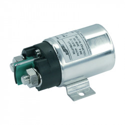
A relay is a device designed to change the state of a circuit (opening and closing), in order to affect other devices in the circuit (it can be the same circuit in which the contactor is located, but it can also be a completely different circuit). Relays are important in industrial processes as they ensure their proper operation.
The flow of current through the coil winding causes the armature to be attracted. When the armature is pulled in, normally closed contacts open, and normally open contacts close. When the voltage is disconnected and the armature drops, the normally open contacts open, and the normally closed contacts close. In the most common relay constructions: coil voltage – 230 VAC or 24 VDC, contact operating current – from 1 to 10A, number of contacts – from one to four changeover pairs.
It should be noted that relay contacts have low current capacity (up to a few amperes). This means that the installed electromagnet is much smaller than in contactors, and the contacts do not have additional arc-chamber extinguishers. A relay has very high durability of several tens of millions of switching cycles.
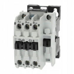
A contactor is a switch whose contacts are closed using an electromagnet and kept in a certain state as long as the coil is supplied with appropriate voltage. When the coil circuit is interrupted, the armature drops (due to the spring action), and the contacts open.
The operating principle and construction are very similar to electromagnetic relays. The essential difference lies in the use of the devices: contactors are used to connect main circuits, e.g. motors, while relays are used in auxiliary circuits such as control or signaling circuits. They also differ in construction, as a contactor may have additional contacts (so-called auxiliary contacts), which can be used for signaling or interlocking.
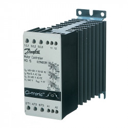
We distinguish AC contactors and DC contactors. Contactors are used for remote switching of three-phase AC circuits in utilization categories AC3 and AC4 (squirrel-cage motors). They can also be used for switching slip-ring motors in category AC2 and heating devices in category AC1. DC contactors have electromagnetic or pneumatic drives, noting that solenoid valves and electromagnets are controlled using DC power. DC contactors are used in fields such as railway traction, tram systems, and battery systems.
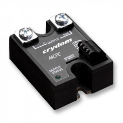
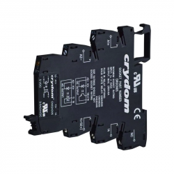
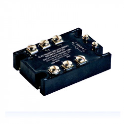
A solid-state relay (SSR) is a component used to manage load current using a semiconductor controlled by an isolated electronic circuit. Galvanic isolation is achieved using an optoelectronic element such as a diode emitting infrared radiation, a photodiode, a phototransistor, or a phototriac.
In the relay’s resting state, when no current flows through the diode, the element is off. When the element is off, its equivalent resistance is very high. When the diode is activated, the photoelement is illuminated. This causes the element to start conducting and switch on the load circuit. This solution is very advantageous, as it allows high switching frequency, ensures high durability of devices, and most importantly, eliminates the phenomenon of electric arc, which can damage equipment.
Parameters characterizing solid-state relays.
In the case of solid-state relays, it should be noted that they have many parameters characterizing various elements of the relay. Generally, the properties can be divided into three subgroups:
Input circuit:
Output circuit:
Operational parameters:
The department dealing with contactors and relays, thanks to its wide assortment, allows engineers to design new devices and operate and maintain existing ones. Our customers have known for many years that we offer products and services of the highest quality. We constantly strive to make the order fulfillment process as convenient as possible for our customers. For this reason, we enable orders to be placed online and by phone.
Also check out fuses available in our offer!
Complementary Products