| Technical data |
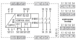
SNO 4063K/SNO 4063KR |
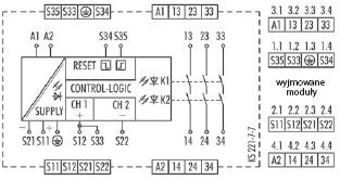
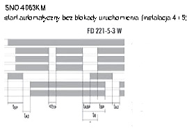
SNO 4063KM |
Function according to EN 60204-1
|
|
|
|
3 LEDs green
|
|
|
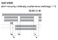
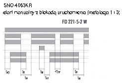
FD 221-5-1 W, FD 221-5-2 W, FD 221-5-3 W
|
|
|
|
|
|
DC 12 V,AC/DC 24V,
AC 115 -120 V,AC 230 V
|
AC/DC 24 V
|
|
|
2,0 W
|
2,1 W
|
|
|
2,4 W/4,4 VA
|
2,5 W/4,6 VA
|
|
|
2,4 VSS
|
|
|
50-60 Hz
|
|
|
0,85-1,1xUN
|
Fuse for control circuit supply
|
|
|
|
|
|
|
|
Rated output voltage (S11 to S21)
|
DC22V
|
Open circuit voltage (only AC devices)
|
<40V
|
|
|
100 mA
|
Short circuit protection / current limitation
|
tak/-
|
tak/250 mA
|
Inputs (S12 / S33, S31 / S22, S34, S35)
|
|
Input voltage range (only for DC devices)
|
DC 17,4 V bis DC 26,4 V
|
Rated current / peak current (safety inputs S12 / S33, S31 / S22)
|
40mA/100mA
|
Rated current / peak current (reset inputs S34, S35)
|
5 mA/50 mA
|
|
|
|
|
Permissible test pulse time tTP / test frequency
|
≤ 1000 us≤10s-1
|
|
Response time tA1 (reset input S34)
|
20 ms - 40 ms
|
|
Response time tA2 (reset input S34)
|
200 ms - 600 ms
|
20 ms - 80 ms
|
|
Response time tA3 (only SNO 4063KR)
|
100ms-400ms
|
|
Minimum ON time tM (reset inputs S34, S35)
|
>80ms
|
|
Locking time tSP
|
-
|
70ms-130ms
|
|
Response time of the lock tASP
|
-
|
>7ms
|
|
Recovery time tW
|
≥100 ms
|
|
Release time tR (K1, K2) with emergency stop
|
<25ms
|
|
Synchronous time tS
|
ca. 200 ms
|
|
Output circuit
|
|
|
|
|
|
|
3 NO contacts, positively driven
|
Rated switching voltage U
|
AC 230V/DC 300V
|
Max. continuous current I per current path
|
6A
|
|
Max. total current of all current paths DC 12 V, AC/ DC 24 VAC
|
12A 8A
|
|
115 -120 V, AC 230 V
|
|
|
Application category according to EN 60947-5 -1 360 h-1
|
AC-15: Ue 230 V AC, Ie 4A / DC-13: Ue24 V DC, Ie 4 A
|
|
3600 h-1
|
AC-15: Ue 230 V AC, Ie 3 A / DC-13: Ue 24 V DC, Ie 2,5 A
|
Short-circuit protection, max. fuse insert
|
6 A class gG or circuit breaker with trigger characteristic B or C
|
|
Mechanical life
|
10x106 switching cycles
|
|
|
|
|
Creepage distances and clearances between the circuits
|
according EN 60664-1
|
|
|
4kV
|
|
|
III
|
Degree of pollution of the device: inside / outside
|
2/3
|
|
|
AC 300 V
|
|
Test voltage Uaff 50 Hz
|
2kV
|
Protection degree according to DIN EN 60529
(housing / terminals)
|
IP40/IP20
|
|
Ambient temperature / storage temperature
|
-25-+55°C/-25-+75°C
|
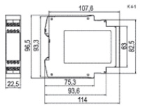
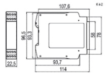
| Dimension diagram |
K 4-1 (screw terminals / K 4-2 (pluggable terminals
|
|
Wire ranges fine-stranded / solid or fine-stranded with ferrules
|
2 x 0,14 - 0,75 mm2/1 x 0,14-2,5 mm2
1 x 0,25 - 2,5 mm2/2 x 0,25 - 0,5 mm2
|
|
Permissible tightening torque
|
0,5 - 0,6 Nm
AWG 18-16 tylko przewody Cu
|
|
Weight
|
0.21 kg (DC device) / 0.25 kg (AC device)
|


 Production line optimization and diagnostics