• Stop category 0 according to EN 60204-1
• Applications up to safety category 2 according to EN 954-1
• Safety category of the device: 4 according to EN 954-1
• Manual or automatic start
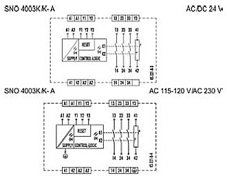
• 3 enabling current paths, 1 signaling current path
• Feedback loop for monitoring external contactors
• Protection of people and machinery
• For immediate interruption of the power supply – stop category 0
• Monitoring of emergency stop applications
• Monitoring of safety gates
• Protective measures in sections of the safety system
Functions
The device is a single-channel switching device for emergency stop applications with self-monitoring on each ON-OFF cycle. It complies with EN 60204-1 and is equipped with positively driven relays.
The device has two reset inputs Y2 (without reset monitoring) or Y3 (with reset monitoring). The relays K1 and K2 are actuated either after the reset button (on Y1-Y3) has been pressed or automatically (bridge Y1-Y2). They become self-locking through their own contacts, if there is an electrical connection between terminal A1 and the
supply voltage (emergency stop button, position switches). After this switch-on phase the enabling current paths are closed and the signaling current path is open. If the electrical connections between terminal A1 and the supply voltage are interrupted, the enabling current paths open and the signaling current path closes. The energized state (self-locking) of the two channels is indicated by a green LED K1, K2. The second green LED indicates that supply voltage has been applied. The set-up of an emergency stop facility after stop category 0 (EN 60204-1) is possible. The device corresponds to category 4 for safety-related parts of controls (EN 954-1).
Proper useThe device is available for monitoring transducers (such as emergency stop buttons or
position switches) that are components of protective equipment on machines and are
used for the purpose of protecting people, material and machines.
• The safety category according to EN 954-1 depends on the external circuitry, the
choice of control devices and their placement on the machine.
• Expansion devices or external contactors with positively driven contacts can be used
to multiply the enabling current paths.
• The device and the contacts must be protected at max. 8 A.
• The emergency stop circuit must be closed before the reset button is activated.
• For connecting magnetic switches with reed contacts or sensors with
semiconductor outputs the peak input current must be considered (see “Technical
data”).
• The devices must be installed in a control cabinet with a protection degree of at
least IP 54.
• With AC supply and single-channel circuitry the maximum cable length for the safety
circuit of the transducers must be considered (see the notes on cable lengths and
“Technical data”
Please also note the information provided by your trade association
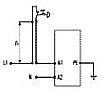
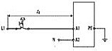
Connection scheme
Max. cable length of the input circuit with AC voltage
Cable data section 1,5 mm2
capacity 150 nF/km
resistance 28 Ω/km
temperature +25 °C
Circuit Alternating current (AC) cable not laid out in parallel,max. length lr:1 km
Tap line max. length of tap line l s and max. line capacity C L depending on supply voltage U
UB 115 230 V
CL 37,5 nF 7,5 nF
lS 250m 50 m