Sie müssen eingeloggt sein
Sie haben kein Konto?
Category
Schaltschränkebau
Design und Montage von Schränken
Installation von Stromversorgungssystemen
Komponenten
Maschinen, die auf Bestellung gebaut werden
F&E-Forschungs- und Entwicklungsarbeiten
Produktionsprozessen Messungsanlagen
Induktoren und Spulen - Reparatur und Regeneration
Induktor-Upgrade
Produktion neuer Induktoren
Wissensbasis
Generatoren für Induktionserwärmung
Renovierung und Modernisierung
Peripheriegeräte
Applikationen
Wartung von Brauchwasserkühlern und Klimaanlagen
Reparaturen und Modernisierung von Maschinen
Reparatur der Leistungselektronik und elektonischen und automatischen Vorrichtungen
Hochspannungsnetzteile für elektrostatische Abscheider – KraftPowercon
Industriedrucker und Etikettierer
UDT-Zertifikat
Fotos dienen nur zu Informationszwecken.
please use latin characters
Options
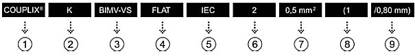
1 - Registered trademark of OMERIN 2 - Symbol of thermoelectric couple 3 - Insulation reference (see main products on next page) 4 - Cable shape:
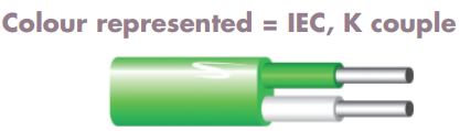
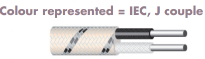
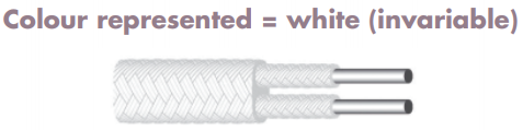
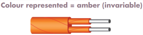
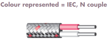
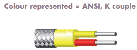
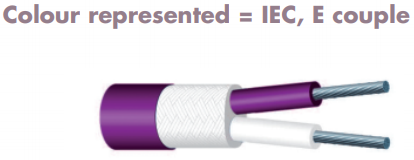
5 - Applicable standard for colour code (see table of standardised colour codes) 6 - Number of conductors = 2 in general:
7 - Core cross-section in mm2 or AWG 8 - Number of strands 9 - Diameter of each strand (in mm)
Interessieren Sie sich für dieses Produkt? Benötigen Sie zusätzliche Informationen oder individuelle Preise?
Enim quis fugiat consequat elit minim nisi eu occaecat occaecat deserunt aliquip nisi ex deserunt.
Zur Wunschliste hinzufügen
Ihre Bewertung der Rezension kann nicht gesendet werden
Kommentar melden
Meldung gesendet
Ihre Meldung kann nicht gesendet werden
Eigenen Kommentar verfassen
COUPLIX- Kabel für Thermoelemente
Ich akzeptiere die allgemeinen Nutzungsbedingungen und Datenschutzbestimmungen. *
* Pflichtfelder
Bewertung gesendet
Ihre Bewertung kann nicht gesendet werden
Für eine optimal Performance, eine reibungslose Verwendung sozialer Medien und aus Werbezwecken empfiehlt dir dieser Laden, der Verwendung von Cookies zuzustimmen. Durch Cookies von sozialen Medien und Werbecookies von Drittparteien hast du Zugriff auf Social-Media-Funktionen und erhältst personalisierte Werbung. Stimmst du der Verwendung dieser Cookies und der damit verbundenen Verarbeitung deiner persönlichen Daten zu?