Overview
The iANT100 is an increased safety antenna and has been designed and approved by ATEX and IECEx for use in Zone 1 / 21 [&] Zone 2 / 22 Hazardous Area Environments. The iANT100 is optimised for use in WLAN installations in both the 2.4GHz and 5GHz spectrums for IEEE802.11 a/b/g/n wireless networks or wireless MESH Ethernet networks. There is also an option which is optimised for use in GSM installations. It can be used with explosion proof Access Points such as the Extronics iWAP103 or the Access Point may be installed in a safe area and just the antenna installed in the hazardous area.
ATEX II 2GD Ex e IIC T6 Gb Ex t IIIC T85°C Db
IECEx Ex e IIC T6 Gb Ex t IIIC T85°C Db
-40°C do 60°C
IP66
Indoor, Outdoor operation The iANT100 is suitable for both indoor and outdoor operation, asit is made from a very rugged and durable material that is resistant to effectively any chemical or contaminant found in industry. Rated to IP66 and with –40C to 60C it can be used in every climate without concerns. From Offshore platforms to chemical or pharmaceutical plants the iANT100 can be relied upon.
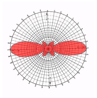
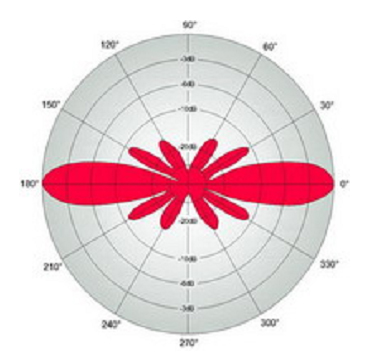
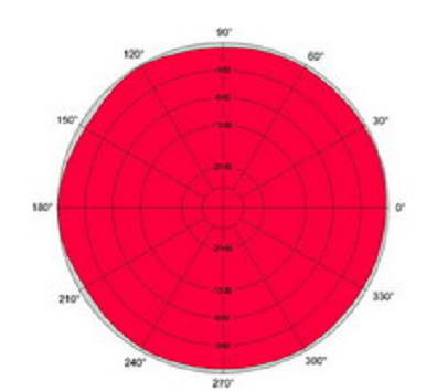
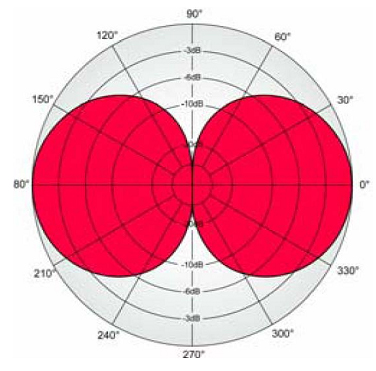
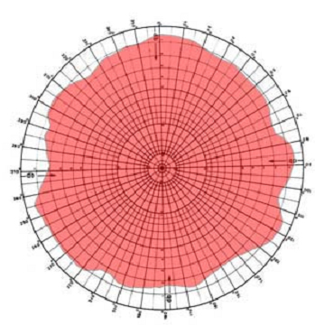
Gain and Direction These antenna offer a high gain as well as being Omni Directional meaning they will give excellent coverage in a plant environment.
Easy Mounting The antenna can be easily mounted and positioned with the aluminium bracket supplied or if preferred an optional 316 stainless steel mounting bracket is available as an extra.
As cable length increases the loss in dB increases
| Cable Length |
Frequency |
| 900MHz |
1800MHz |
2000MHz |
2500MHz |
5000MHz |
5800Mhz |
| 1 meters |
0.36dB |
0.53dB |
0.55dB |
0.62dB |
0.91dB |
0.98dB |
| 3 meters |
1.07dB |
1.58dB |
1.66dB |
1.87dB |
2.72dB |
2.94dB |
| 5 meters |
1.78dB |
2.63dB |
2.77dB |
3.12dB |
4.53dB |
4.91dB |
| 8 meters |
2.84dB |
4.20dB |
4.43dB |
4.99dB |
7.24dB |
7.85dB |
| 10 meters |
3.55dB |
5.25dB |
5.54dB |
6.24dB |
9.1dB |
9.81dB |
Specification
| Parameter |
iANT100-24
|
iANT100-58
|
iANT100-GSM-QB
|
| Power |
Max power 1 Watt continuous
ATEX: Maximum threshold power must not exceed 2W EIRP when taking antenna gain into account. Software RF Power control settable by the user is not permitted |
Max power 1 Watt continuous
ATEX: Maximum threshold power must not exceed 2W EIRP when taking antenna gain into account. Software RF Power control settable by the user is not permitted |
Max power 1 Watt continuous
ATEX: Maximum threshold power must
not exceed 2W EIRP when taking antenna gain into account. Software RF
Power control settable by the user is not permitted
|
| Dimensions |
210mm Length, 38mm Diameter |
210mm Length, 38mm Diameter |
210mm Length, 38mm Diameter |
| Weight |
365g |
365g |
365g |
| Connections |
Straight Reverse Polarity BNC (Other connector types available on request) |
Straight Reverse Polarity BNC (Other connector types available on request) |
Straight Reverse Polarity BNC (Other connector types available on request) |
Cable Sealed
Lead Length |
Supplied as 5 metre as standard, other lengths on request |
Supplied as 5 metre as standard, other lengths on request |
Supplied as 5 metre as standard, other lengths on request |
| Frequency |
2350-2550MHz |
5150—5875MHz |
GSM 850 / 900 / 1800 / 1900 / 2100 |
| Bandwidth |
+/- 100MHz |
Bands A, B i C |
|
| Impedance |
50 Ohm |
50 Ohm |
50 Ohm |
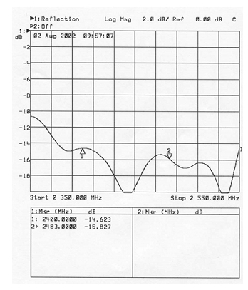
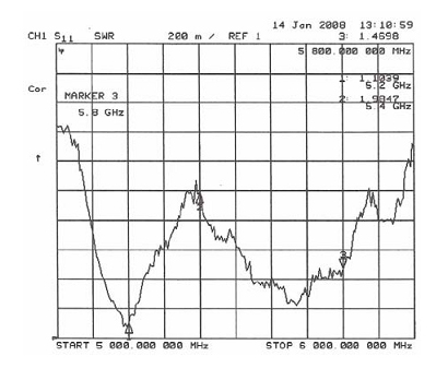
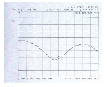
| Return Loss |
Better than –11 dB over bandwidth |
Better than –12 dB over bandwidth |
Better than –11 dB over bandwidth |
| Gain |
5 dBi |
8 dBi |
2 dBi |
Horizontal
Radiation
Pattern |
Omni Directional |
Omni Directional |
Omni Directional |
Vertical 3dB
Beam-width |
Approx 34° |
Approx 16° |
Approx 80° |
Radiating
Element |
Brass tubing, copper plated steel rod |
PCB and Brass tubing. |
PCB |
| Ambient Temperature |
-40°C do 60°C |
-40°C do 60°C |
-40°C do 60°C |
| IP Rating |
IP66 |
IP66 |
IP66 |
Certification
Number |
Sira 11ATEX3100X
IECEx SIR 11.0045X |
Sira 11ATEX3100X
IECEx SIR 11.0045X |
Sira 11ATEX3100X
IECEx SIR 11.0045X |
ATEX
Certification |
II 2GD Ex e IIC T6 Gb (Ta = -40°C do +60°C)
Ex t IIIC T85°C Db IP66 |
II 2GD Ex e IIC T6 Gb (Ta = -40°C do +60°C)
Ex t IIIC T85°C Db IP66 |
II 2GD Ex e IIC T6 Gb (Ta = -40°C do +60°C)
Ex t IIIC T85°C Db IP66 |
| |
Ex e IIC T6 Gb (Ta = -40°C do +60°C)
Ex t IIIC T85°C Db IP66 |
Ex e IIC T6 Gb (Ta = -40°C do +60°C)
Ex t IIIC T85°C Db IP66 |
Ex e IIC T6 Gb (Ta = -40°C do +60°C)
Ex t IIIC T85°C Db IP66 |
Ordering Information
iANT 100 Zone 1 Omni Directional Antenna 1 iANT100-[#1]-[#2]-[#3]-[#4]-[#5]-[#6]-[#7] -[#8]
Specify option [#1] - Frequency
| 2,4GHz |
24 |
| 5GHz |
58 |
| GSM Quad-band |
QB |
Specify option [#2] - Cable Length
| 5m |
5 |
| Special cable length |
S |
Specify option [#3] - Connector type
| Straight N-type male * |
1 |
| Right angle N-type male (Recommended for use with Extronics iWAP103/iWAP106) * |
2 |
| Straight reverse-polarity SMA male |
3 |
| Right-angle reverse-polarity TNC male |
4 |
| Straight reverse-polarity BNC male |
5 |
| No connector fitted |
6 |
* N.B. It is impossible for a straight or right angle N-type connector fitted to the cable to pass through the enclosure entry for an M20 cable gland. Either the connector must be fitted after passing the cable through the enclosure hole, or a larger M25 enclosure entry should be used with a suitable thread reducer. This permits the N-type connector to pass through the hole. Select either option #4 (N) or option#7 (2).
Note that the Extronics iWAP103/iWAP106 issupplied with M25 cable entries and M25-M20 thread reducers as standard.
Specify option [#4] - Connector fitting
| Selected connector fitted |
F |
| Crimp connector supplied separately for customer fitting (RG58 crimp tool required) |
N |
Specify option [#5] - Cable Gland
| No gland fitted |
1 |
| Fitted with CR-UB-NP-16-M20 Ex d cable gland |
2 |
| Fitted with CR-UB-NP-16-075-NPT Ex d cable gland |
3 |
| Fitted with customer-supplied cable gland |
4 |
Specify option [#6] - Cable Gland Position
| Not applicable |
X |
| Cable gland installed at default distance from antenna (cable length minus 0.45m) |
D |
| Special cable gland position, specify on order |
S |
(Cable gland must be a minimum of 0.65m from the antenna, and a minimum of 0.45m is recommended between the gland and connector)
Specify option [#7] - Gland thread reducer supplied
| No thread reducer supplied |
1 |
| CR-UB-NP-16-M20 Ex d cable gland supplied with M25 - M20 thread reducer |
2 |
Specify option [#8] - Mounting bracket
| Supplied with standard aluminium wall mounting bracket |
1 |
| Supplied with 316 stainless steel wall mounting bracket |
2 |