| Technical data |
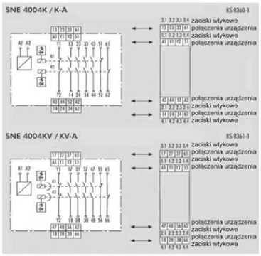
SNE 4004K/SNE 4004KV |
Function according to EN 60204-1
|
Emergency stop expansion relay
|
|
|
|
|
|
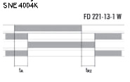
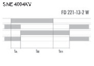
FD 221-13-1 W, FD 221-13-2 W
|
|
|
min typ
|
max
|
|
Rated voltage UN SNE 4004K
|
AC/DC 20,4 V AC/DC 24 V
|
AC/DC 26,4 V
|
|
Rated voltage UN SNE 4004KV
|
DC 20,4 DC 24 V
|
DC 26,4 V
|
|
Rated consumption DC
|
1,0 W
|
|
Rated consumption AC
|
1,5 W/2,7 VA
|
|
Residual ripple DC
|
|
2,4 VSS
|
|
Rated frequency AC
|
50 Hz
|
60Hz
|
|
Rated current / peak current
|
65 mA/1000 mA
|
80 mA/1800 mA
|
|
Response time tA
|
20 ms
|
|
Release time tR2 SNE 4004K with emergency stop
|
40 ms
|
|
Minimum ON time tM SNE 4004KV
|
75 ms
|
|
Release time tR1 SNE 4004KV (buffered)
|
0,5 s/1 s/2 s/3 s
|
|
Mean value of the error SNE 4004KV
|
±20 %
|
|
|
±2 %
|
|
Feedback current path Y1/Y2
|
1 NC contact, positively driven
|
Rated switching voltage Un
|
DC 24 V
|
Max. continuous current In
|
0,1 A
|
|
|
|
|
|
|
|
|
4 NO contacts, positively driven
|
Rated switching voltage Un
|
AC/DC 230 V
|
|
Max. continuous current In/max. total current
|
6 A/12 A
|
|
Application category according to EN 60947-5-1 3600 h-1
360 h-1
|
AC-15: Ue 230 V, Ie 6 A / DC-13: Ue 24 V, Ie 3 A
DC-13: Ue 24 V, Ie 6 A
|
Short-circuit protection, max. fuse insert
|
6 A class gG or circuit breaker with trigger characteristic B or C
|
|
|
|
|
|
|
|
|
2 NC contacts, positively driven
|
Rated operating voltage U
U N
|
AC/DC 230 V
|
Max. continuous current In
|
2 A
|
|
|
|
|
|
|
Creepage distances and clearances between the circuits
|
według EN 60664-1
|
|
Overvoltage category
|
III
|
|
Rated impulse voltage
|
4 kV
|
|
Rated voltage
|
AC 300 V
|
|
Degree of pollution of the device: inside / outside
|
2/3
|
|
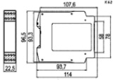
Protection degree according to DIN EN 60529 (housing / terminals)
|
IP 40/IP 20
|
Ambient temperature / storage temperature
|
-25 - +55 °C/-25 - +75 °C
|
|
|
K 4-1 (screw terminals)/ K 4-2 (pluggable terminals)
|
|
Rated cross sections fine-stranded/solid
or fine-stranded with ferrules
|
2x0,14 - 0,75 mm2/1x0,14 - 2,5 mm2
1x0,25 - 2,5 mm2/2x0,25 - 0,5 mm2
|
Permissible tightening torque
|
0,5 – 0,6 Nm
|
| Weight |
0,20 kg
|
|
Accessories
|
-
|
|
Approvals
|
|