Electromagnetic compatibility (EMC) refers to the inter-relationship between various electrical/electronic systems within a component as well as the relationship between the component and the electromagnetic environment.
There are three causes of problems which may occur individually or together:
Effects of Conducted interference
Conducted interference occurs as a result of an unintentional effect on an electrical system of voltage drops, pulses/spikes and high frequency currents. (eg. electric motors)
Effects of Near field
The near field of a system is influenced by galvanic, inductive and capacitive coupling resulting in emissions in close proximity to the source.
Effects of Far field
The far field of a system is influenced by environmental factors (eg. radio and TV transmitters) which in turn can influence the system.
An electrical/electronic system may be both the source and the victim of electromagnetic interference (EMI).
The near field and the far field are the most relevant for gasket shielding, we shall therefore concentrate on these aspects.
Typically a generating source will produce a wave with two components, a magnetic field and an electric field.
The relationship between the magnetic (H) field and the electrical (E) field is dependent upon the nature of the source and the distance from that source.
The ratio of the two fields is important and is expressed as wave impedance Z.
Certain sources generate strong magnetic fields and are said to have low impedance.
Similarly a high impedance source generates electric fields.
At long distances from the source the components of E and H become equal. The wave is then classed as plane wave.
This relationship is applicable to a variety of devices that generate electromagnetic waves, from those whose function it is to do so, for example radio transmitters and microwaves, to those which create it as a by product, for example power cables.
When a wave encounters an object some energy will be reflected, some will be absorbed (converted to heat and create residual internal current flow) and a certain amount will leak through.
Many factors govern the proportions of the above relationship; the impedance of the wave and the object is particularly important. The greater the difference, the more energy is reflected.
When the wave impedance is low (ie. magnetic field) a greater proportion of energy is absorbed. This is the main reason magnetic fields are difficult to shield effectively.
Any internal current flow can create a field on the internal side of the barrier.
Therefore, the ideal method of shielding is to reflect the wave energy. Any absorbed energy can create residual current.
Shielding effectiveness is a measure of the attenuation or reduction of energy across a component or test piece. The unit is a decibel or dB.
The relationship is logarithmic, that is:
N dB = 10 log P1/P2, where the fraction P1/P2 is a unitless power ratio of the relevant values of measurement.
Electromagnetic spectrum
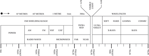
RFI - Radio Frequency Interference: Unwanted radiated electronic noise 10kHz to 1000MHz
EMP - Electromagnetic pulse: Broadband, High Intensity Transient Phenomena, such as lightning or nuclear explosion (NEMP).
HERF - High Energy Radio Frequency
EMI - Electromagnetic Interference: DC to 300GHz
ESD - Electrostatic Discharge: A transient phenomena involving static electricity
Gasket Shielding Performance
Shielding effectiveness is typically expressed in dB mean attenuation, i.e., the ratio of energy loss. Throughout the industry, there are many specifications, e.g., MIL-G-83528, MIL-STD-285 and SAE-ARP-1705, each one having a particular relevance to a specific field of operation. Space does not permit us to publish all the data available, but the charts below show typical shielding effectiveness values for differing materials.
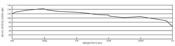
Life Performance
Shows typical attentuation values across the frequency band including extrapolated life values.
Test method: transfer impedance to SAE-ARP-1705. Material: silver aluminium silicone (TC Ref 1D/1 and 3D).
Test jig material: 6061 aluminium with chromate surface.

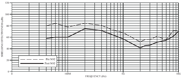
Environmental Performance
Refers to shielding effectiveness to MIL-G-83528/Mil-285 procedure for silver/aluminium loaded silicone (TC Ref 1D and 3D), before and after SO2 laden 5% salt spray (192 hours immersion).
Printed Material Performance
Relates to mean attenuation to SAE-ARP-1705 for Nickel/Graphite loaded silicone (TC Ref 3J/2)
Guide to Conductive Elastomers
Base Polymers available are: Silicone and Fluorosilicone
Silver/Copper (Ag/Cu)grades are tan in colour and are compounded to offer the greatest level of shielding performance. They also have excellent resistance to EMP and offer very high current transfer plus good thermal transfer characteristics. Working temperature range -50° to +125°C.
Silver/Aluminium (Ag/Al) grades are tan in colour and selected on the basis of their excellent shielding performance and low density for weight sensitive applications. Working temperature -50° to +160°C..
Silver/Glass (Ag/Glass)grades are tan in colour and have the lowest density of all the high performance grades, specifically recommended for application where weight is critical and shielding requirements are less demanding. Silver glass is not recommended in high current transfer applications such as EMP. Working temperature range -50° to +160°C.
Czyste srebro (Ag)loaded materials are tan in colour and exhibit the highest level of electrical conductivity with good shielding performance. This grade is particularly useful for offering a low resistance to current flow. Working temperature range -50° to +160°C.
Silver/Nickel (Ag/Ni) loaded grades are tan in colour offering excellent shielding performance. Generally an expensive material due to inherent high cost and high S.G. Working temperature range -50° to +160°C.
Nickel/Graphite (Ni/Gr)loaded grades are grey in colour and are selected for their good shielding performance and their resistance to galvanic corrosion.
Working temperature range -50° to +160°C.
Aluminium Compatible loaded silicone is black in colour and available as a printing grade only. The material offers good levels of shielding with excellent galvanic compatibility in contact with aluminium in salt spray environments.
Working temperature range -50° to +160°C.
Fluorosilicone is not available on printing systems.
Aspects of Corrosion[&] Design Recommendations
The Problem and the Dilemma
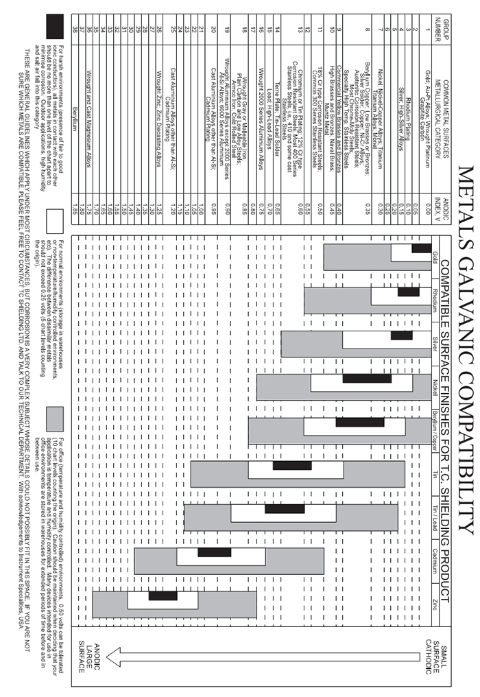
To achieve a high reflection loss at a sealing interface in an enclosure, and thus effective sealing and shielding of the joint, a low impedance material is required. A low impedance material is one which conducts electricity well. Good conductors such as silver and nickel have very low or even negative electrode potentials. When they are placed in an electrolyte such as sea water with dissimilar metals such as steel or aluminium, electrolytic action takes place, causing corrosion and degraded shielding at the joint interface. According to the potential difference between the two metals, one electrode in the galvanic cell will be the donor and become gradually eroded.
The potential diffference (PD) between metals and shielding materials commonly used in enclosures is normally expressed in volts. Typical values for the PD of metals are measured using a standard calomel electrode in sea water (see table for values).
T C Shielding has carried out tests on the most commonly used conductive elastomers and values for their PD are listed alongside the values for various metals (see table on page 10).
The industry norm for acceptable PD between differing metals in a salt spray environment is 0.5v and in a military environment 0.3v is often used.
Thus the potential for galvanic corrosion can exist in applications when faced with utilising highly conductive metal loaded elastomers such as silver, and to a lesser extent nickel and carbon, in contact with aluminium.
The Solution
Two potential solutions exist for the designer to minimise or totally overcome corrosion problems.
- Choice of elastomer is made giving due consideration to the level of shielding required, and other matters such as commercial implications.
Consideration should then be given to using a metallic coating on the surface of the enclosure hardware in contact with the seal.
In the case of silver based elastomer materials, the hardware should be silver plated. In the case of nickel graphite or carbon, nickel plating
is recommended.
Nickel plating can be considered a possible compromise with silver based elastomer materials
- Duo Seal’ design option
Where design constraints allow, it may be possible to accommodate a ‘duo-seal’ design of jointed ring. This principle is based on a traditional groove captivating
a co-extruded profile which comprises two sealing elements. The outer sealing element is a silicone or fluorosilicone material that effectively seals the outside
environment and eliminates the potential for corrosion. The inner sealing element comprises conductive elastomer to achieve low impedance electrical contact, and give shielding of the enclosure and joint interface.
Choice of materials should be made based on commercial and performance considerations relating to the application and design.
Metals galvanic compatibility
Environmental Compatibility
| |
|
Enclosure material |
Tc
Ref |
Filler type
|
aluminium
alloys
|
magnesium
alloys
|
stainless
steel
|
copper
alloys
|
cadmium
plating
|
tin
plating
|
| A |
SILVER/NICKEL
|
X |
X |
• |
• |
X |
⌈ |
| B |
SILVER/COPPER
|
X |
X |
• |
• |
X |
X |
| D |
SILVER/ALUMINIUM
|
⌈ |
⌈ |
• |
• |
⌈ |
⌈ |
| K |
INERT ALUMINIUM (A1 COMPATIBLE)
|
• |
⌈ |
• |
• |
⌈ |
• |
| I |
SILVER/GLASS |
X |
X |
• |
• |
X |
⌈ |
| G |
SILVER
|
X |
X |
• |
• |
X |
⌈ |
| J |
NICKEL/GRAPHITE
|
⌈ |
⌈ |
• |
• |
⌈ |
• |
| |
|
Enclosure material
|
| P/N |
Materiał zatopiony |
nickel
plating
|
chromium
plating
|
silver
plating
|
zinc plated
galvanised
steel
|
titanium
|
| A |
SILVER/NICKEL |
• |
• |
• |
X |
• |
| B |
SILVER/COPPER
|
⌈ |
• |
• |
X |
• |
| D |
SILVER/ALUMINIUM
|
⌈ |
• |
• |
⌈ |
• |
| K |
INERT ALUMINIUM (A1 COMPATIBLE)
|
• |
• |
• |
⌈ |
• |
| I |
SILVER/GLASS |
• |
• |
• |
X |
• |
| G |
SILVER
|
• |
• |
• |
X |
• |
| J |
NICKEL/GRAPHITE
|
• |
• |
• |
⌈ |
• |
• - GOOD, ⌈ - SATISFACTORY, X NOT RECOMMENDED
Flammability of Silicones
When silicone rubber burns as it would in an intense fire, the polymer decomposes to form silica which, along with the fillers, forms a non-conducting ash.
While burning, it will yield a comparatively low level of smoke. Carbon Monoxide will be a component of the smoke. However, unlike other materials containing halogens, sulphur or nitrogen, it cannot evolve hydrogen chloride, fluorides, sulphur dioxide, nitric oxide or other noxious chemicals which can irritate the eyes, nose or throat.
Silicone rubber is capable of withstanding temperatures of up to 500°C for several minutes while still exhibiting good insulation properties. Silicones typically have a flame rating of UL94 HB when tested in accordance with the underwriters laboratory Flame Test (UL94).
Typical comparative smoke generation values for a range of polymers are as given in the chart below:
| Material |
Dm |
Tc(min) |
GASES INVOLVED |
| CO |
HCL |
HCN |
SO2 |
| Silicone (MVQ) |
43 |
7 |
yes |
no |
no |
no |
| Polyvinyl Chloride (PVC) |
180 |
1,4 |
yes |
yes |
trace |
no |
| Polychlorprene (CR) |
161 |
1,6 |
yes |
yes |
trace |
no |
| Ethylene Propylene (EPDM) |
196 |
1,1 |
yes |
yes |
no |
yes |
In the table above Dm represents Maximum Specific Optical Density or maximum smoke accumulation over a 20 minute period. Tc is the time taken to reach a Specific Optical Density of 16 (i.e., light transmittance of 16%).
Introduction
Conductive rubber seals and gaskets can be expected to provide excellent service over many years. However, one can expect certain physical properties to change during storing - in certain cases poor storage can render the rubber unusable due to excessive degradation of the physical or electrical properties.
The purpose of this document is to provide general recommendation on the storage of conductive rubbers in all forms, to ensure that any degradation is kept to a minimum.
Certain factors have a major effect on shelf life. Below are listed these factors in more detail.
Temperature
Recommended range 5° to 25°C
Below 5°C no permanent damage will be experienced, but the product may be more rigid - hence care in handling. At elevated temperatures above 25°C deterioration may occur more readily.
Light
Under no circumstances should the product be subject to light - natural or artificial. The product is to be stored in light proof, sulphur free packaging.
Humidity
<75% Relative humidity without condensation.
Contact with other Materials
During storage the product should not come into contact with any of the following:-
1. Solvents
2. Oils and greases
3. Material containing sulphur
4. Metals, particularly copper and its alloys
5. PVC
6. Different rubber materials
The technique of extruding conductive elastomers has a wide range of benefits. This area of technology utilises both polymer and profile development, solving a wide range of shielding and sealing problems. Below is a list of the major advantages of this process:
- Profiles can be developed for areas where low closure forces exist.
- Profiles can be mitre jointed to ease assembly and prevent leakage (both RF and
Environmental).
- Profiles can be butt joined in the form of ‘O’ rings to ease assembly, prevent
emissions, susceptibility and effects on environmental sealing.
- Product can be adhesive backed (dependent on profile type).
- Product can have rivet holes (dependent on profile type).
- Secondary environmental sealing can be incorporated into gasket.
- Two part duo systems can be manufactured to give complete environmental protection
and thus eliminate the galvanic corrosion potential.
- Silicones and fluorosilicones plus wide range of conductive fillers.
Standard or special extrudate can be supplied in a variety of forms, cut to a discrete length, continuous length or fabricated. Fabrication involves joining the extrudate to form a continuous seal. The joint is fully vulcanised with a conductive jointing material. Fabrication covers a multitude of configurations from a simple ‘O’ ring to complex panel flange gaskets up to 1.5 metres in size.
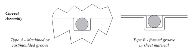
Instalacja
To effect a mechanical and electrical seal the gasket needs to be compressed. Insufficient compression can result in fluid leakage and poor electrical performance. Excessive compression will result in physical and electrical failure of the joint. The best method for controlling compression is by locating the gasket in a groove - typical configurations are shown below.
If grooves are not possible, compression control can be achieved by alternative means, e.g., shouldered fixings, washers, spacer plates and in certain cases limiters built into the gasket.
Compression
Gaskets have a finite working compression range. Each sectional profile has its own loading characteristic primarily due to its stiffness and shape. Conductive ‘O’ rings typically have a range between 10 and 25%. Hollow profiles have very low load requirements and are therefore ideally suited for applications where the flange is insufficiently stiff or where low clamping loads are prevalent - depending upon section, hollow profiles have a compression range of 7.5 to 50%.
Groove dimensions
When assembling gaskets into fully enclosed grooves it is important to remember that rubbers behave as ‘incompressible’ fluids. Therefore sufficient allowance has to be given for volume displacement.
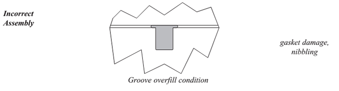
As a general guide allow a minimum of 5% free volume at extremes of tolerance.
| General Description |
| EcE Material Reference (Type) |
1A/1 |
1B/1 |
1B/2 |
1D/1 |
1I/1 |
1I/3 |
1I/4 |
| Elastomer Type (Sil - Silicone, F/Sil - Fluorosilicone) |
Sil |
Sil |
Sil |
Sil |
Sil |
Sil |
Sil |
| Filler Material (Silver on Aluminium,Nickel,Copper,Glass [&] Nickel Graphite) |
Ag/Ni |
Ag/Cu |
Ag/Cu |
Ag/Al |
Ag/Glass |
Ag/GlassA |
g/Glass |
| Colour |
tan |
tan |
tan |
tan |
tan |
tan |
tan |
| Electrical Properties |
Tol |
Test method |
|
Volume Resistivity (ohm.cm)
(as supplied) |
Max |
|
0,047 |
0,005 |
0,008 |
0,008 |
0,05 |
0,005 |
"0.050 - |
| 0.100" |
| Shielding Effectiveness (dB) |
|
MIL-G-83528
MIL 285 |
70 |
70 |
70 |
70 |
50 |
55 |
55 |
| 200 KHz (H-Field) |
| 100 MHz (E-Field) |
|
105 |
115 |
115 |
110 |
65 |
95 |
95 |
| 500 MHz (E-Field) |
|
105 |
115 |
115 |
105 |
70 |
95 |
90 |
| 2 GHz (Plane Wave) |
|
100 |
115 |
115 |
100 |
70 |
95 |
90 |
| 10 GHz (Plane Wave) |
|
100 |
115 |
115 |
100 |
65 |
95 |
90 |
| Physical Properties |
| Specific Gravity (g/cmΔ) |
±5% |
ASTM D-792 |
4,32 |
3,32 |
3,02 |
2,11 |
1,85 |
1,8 |
1,75 |
| Hardness (Shore A) |
± 5 |
ASTM D-2240 |
65 |
75 |
61 |
70 |
65 |
65 |
60 |
| Tensile Strength (MPa) |
Min |
ASTM D-412 |
1,25 |
1,25 |
1 |
0,9 |
0,55 |
0,35 |
0,9 |
| Elongation (%) |
Min |
ASTM D-412 |
100 |
100 |
100 |
100 |
60 |
75 |
80 |
| Compression Set (%) |
Max |
ASTM D-395 |
30 |
30 |
30 |
30 |
30 |
30 |
30 |
| Upper Operating Temperature (°C) |
- |
|
160 |
125 |
125 |
160 |
160 |
160 |
160 |
| Lower Operating Temperature (°C) |
- |
ASTM D-1329 |
-50 |
-50 |
-50 |
-50 |
-50 |
-50 |
-50 |
| General Description |
| EcE Material Reference (Type) |
1J/2 |
1J/3 |
1D/2 |
2A |
2B |
2D |
2J |
| Elastomer Type (Sil - Silicone, F/Sil - Fluorosilicone) |
Sil |
Sil |
Sil |
F/Sil |
F/Sil |
F/Sil |
F/Sil |
| Filler Material |
Ni/Gr |
Ni/Gr |
Ag/Al |
Ag/Ni |
Ag/Cu |
Ag/Al |
Ni/Gr |
| Colour |
|
|
grey |
grey |
tan |
tan |
tan |
Lt Grn |
Dk Grn |
| Electrical Properties |
Tol |
Test Method |
|
| Volume Resistivity (ohm.cm)(as supplied) |
Max |
|
0,05 |
"0.100 - |
0,008 |
0,005 |
0,005 |
0,01 |
0,05 |
| 0.500" |
| Shielding Effectiveness (dB) |
|
MIL-G-83528
MIL 285 |
70 |
70 |
70 |
75 |
75 |
70 |
70 |
| 200 KHz ((H-Field)) |
| 100 MHz (E-Field)) |
|
95 |
95 |
100 |
110 |
110 |
110 |
100 |
| 500 MHz (E-Field) |
|
90 |
90 |
100 |
110 |
120 |
105 |
100 |
| 2 GHz (Plane Wave) |
|
90 |
90 |
100 |
105 |
120 |
100 |
100 |
| 10 GHz (Plane Wave) |
|
90 |
90 |
100 |
100 |
120 |
100 |
100 |
| Physical Properties |
| Specific Gravity (g/cm∆ |
±5% |
ASTM D-792 |
2,45 |
1,99 |
2 |
4,6 |
5 |
2,7 |
3,25 |
| Hardness (Shore A) |
± 5 |
ASTM D-2240 |
80 |
60 |
65 |
80 |
75 |
70 |
80 |
| Tensile Strength (MPa) |
Min |
ASTM D-412 |
2 |
1 |
0,9 |
1,25 |
1,25 |
0,55 |
0,75 |
| Elongation (%) |
Min |
ASTM D-412 |
150 |
100 |
175 |
100 |
100 |
100 |
100 |
| Compression Set (%) |
Max |
ASTM D-395 |
30 |
30 |
30 |
30 |
30 |
30 |
30 |
| Upper Operating Temperature (°C) |
- |
|
160 |
160 |
160 |
160 |
125 |
160 |
160 |
| Lower Operating Temperature (°C) |
- |
ASTM D-1329 |
-50 |
-50 |
-50 |
-50 |
-55 |
-55 |
-55 |
NOTE:
Elongation is not electrically related. Materials should not be stretched over 3.0% to ensure electrical properties are not negated.
Extruded ‘O’ Ring Gaskets Installation Guidelines
‘O’ Rings are extremely reliable and cost effective seals provided care is taken in the installation. Many similarities exist between conductive and non conductive ‘O’ Rings and how they are utilised eg. lead in chamfers, removal of sharp edges on hardware etc.
However, in certain aspects conductive ‘O’ Rings require special attention. Below are the most important factors:
Stretching
During assembly or when finally located, the stretch should not exceed 5% of the original inside diameter. Above this value filler dispersal can be re-oriented resulting in degradation of electrical properties.
Compression
As with stretching above, compression should not exceed 25% for solid sections. For hollow sections (i.e.. tube) 100% compression of void is acceptable.
Joints
To produce ‘O’ Rings from hollow forms it is necessary to join extrudate, T C Shielding uses special materials and methods in which the joining material is inherently conductive - not simply an adhesive. The joint itself is fully vulcanised and exhibits comparable characteristic to the extrudate.
Galvanic Corrosion
The choice of ring material relative to the mating parts is important, particularly in hostile environments e.g.. marine. Please refer to T C Shielding compatibility charts for information (pages 8, 9, 10 and 11)..
Cleanliness
Conductive materials are susceptible to both chemical and particulate contamination during handling. This can have an effect on electrical properties. It is recommended that clean cotton gloves are used during assembly.
Storage
As with all elastomeric products storage is important. With conductive materials certain aspects (e.g.. light) can be particularly detrimental to electrical properties. Please refer to T C Shielding data sheets for further information.


