-
-
-
Category
-
Semiconductors
- Diodes
- Thyristors
-
Electro-insulated Modules
- Electro-insulated Modules | VISHAY (IR)
- Electro-insulated Modules | INFINEON (EUPEC)
- Electro-insulated Modules | Semikron
- Electro-insulated Modules | POWEREX
- Electro-insulated Modules | IXYS
- Electro-insulated Modules | POSEICO
- Electro-insulated Modules | ABB
- Electro-insulated Modules | TECHSEM
- Go to the subcategory
- Bridge Rectifiers
-
Transistors
- Transistors | GeneSiC
- SiC MOSFET Modules | Mitsubishi
- SiC MOSFET Modules | STARPOWER
- Module SiC MOSFET ABB’s
- IGBT Modules | MITSUBISHI
- Transistor Modules | MITSUBISHI
- MOSFET Modules | MITSUBISHI
- Transistor Modules | ABB
- IGBT Modules | POWEREX
- IGBT Modules | INFINEON (EUPEC)
- Silicon Carbide (SiC) semiconductor elements
- Go to the subcategory
- Gate Drivers
- Power Blocks
- Go to the subcategory
- Electrical Transducers
-
Passive components (capacitors, resistors, fuses, filters)
- Resistors
-
Fuses
- Miniature Fuses for electronic circuits - ABC & AGC Series
- Tubular Fast-acting Fuses
- Time-delay Fuse Links with GL/GG & AM characteristics
- Ultrafast Fuse Links
- Fast-acting Fuses (British & American standard)
- Fast-acting Fuses (European standard)
- Traction Fuses
- High-voltage Fuse Links
- Go to the subcategory
- Capacitors
- EMI Filters
- Supercapacitors
- Power surge protection
- TEMPEST emission revealing filters
- Surge arrester
- Go to the subcategory
-
Relays and Contactors
- Relays and Contactors - Theory
- 3-Phase AC Semiconductor Relays
- DC Semiconductor Relays
- Controllers, Control Systems and Accessories
- Soft Starters and Reversible Relays
- Electromechanical Relays
- Contactors
- Rotary Switches
-
Single-Phase AC Semiconductor Relays
- AC ONE PHASE RELAYS 1 series| D2425 | D2450
- One phase semiconductor AC relays CWA and CWD series
- One phase semiconductor AC relays CMRA and CMRD series
- One phase semiconductor AC relays - PS series
- Double and quadruple semiconductor AC relays - D24 D, TD24 Q, H12D48 D series
- One phase semiconductor relays - gn series
- Ckr series single phase solid state relays
- One phase AC semiconductor relays for DIN bus - ERDA I ERAA series
- 150A AC single phase relays
- Rail Mountable Solid State Relays With Integrated Heat Sink - ENDA, ERDA1 / ERAA1 series
- Go to the subcategory
- Single-Phase AC Semiconductor Relays for PCBs
- Interface Relays
- Go to the subcategory
- Cores and Other Inductive Components
- Heatsinks, Varistors, Thermal Protection
- Fans
- Air Conditioning, Accessories for Electrical Cabinets, Coolers
-
Batteries, Chargers, Buffer Power Supplies and Inverters
- Batteries, Chargers - Theoretical Description
- Modular Li-ion Battery Building Blocks, Custom Batteries, BMS
- Batteries
- Battery Chargers and Accessories
- Uninterruptible Power Supply and Buffer Power Supplies
- Inverters and Photovoltaic Equipments
- Energy storage
- Fuel cells
- Lithium-ion batteries
- Go to the subcategory
-
Automatics
- Spiralift Lifts
- Futaba Drone Parts
- Limit Switches, Microswitches
- Sensors, Transducers
-
Infrared Thermometers (Pyrometers)
- IR-TE Series - Water-proof Palm-sized Radiation Thermometer
- IR-TA Series - Handheld Type Radiation Thermometer
- IR-H Series - Handheld Type Radiation Thermometer
- IR-BA Series - High-speed Compact Radiation Thermometer
- IR-FA Series - Fiber Optic Radiation Thermometer
- IR-BZ Series - Compact Infrared Thermometers
- Go to the subcategory
- Counters, Time Relays, Panel Meters
- Industrial Protection Devices
- Light and Sound Signalling
- Thermographic Camera
- LED Displays
- Control Equipments
- Go to the subcategory
-
Cables, Litz wires, Conduits, Flexible connections
- Wires
- Cable feedthroughs and couplers
- Litz wires
-
Cables for extreme applications
- Extension and Compensation cables
- Thermocouple cables
- Connection cables for PT sensors
- Multi-conductor wires (temp. -60C to +1400C)
- Medium voltage cables
- Ignition wires
- Heating cables
- Single conductor cables (temp. -60C to +450C)
- Railway cables
- Heating cables Ex
- Cables for the defense industry
- Go to the subcategory
- Sleevings
-
Braids
- Flat Braids
- Round Braids
- Very Flexible Flat Braids
- Very Flexible Round Braids
- Cylindrical Cooper Braids
- Cylindrical Cooper Braids and Sleevings
- Flexible Earthing Connections
- PCV Insulated Copper Braids (temp. up to 85C)
- Flat Aluminium Braids
- Junction Set - Braids and Tubes
- Steel Braids
- Go to the subcategory
- Traction Equipment
- Cable Terminals
- Flexible Insulated Busbars
- Flexible Multilayer Busbars
- Cable Duct Systems
- Go to the subcategory
- View all categories
-
Semiconductors
-
-


Bolt Torque Optimization for Discrete IGBTs: A Comprehensive Guide

In the semiconductor field, insulated gate bipolar-unipolar transistors (IGBTs) play a key role in numerous electronic applications, from power inverters to motor drives. Achieving optimal thermal performance in these systems is crucial to ensuring operational reliability and efficiency. This article delves into the subtle world of screw torque for discrete IGBTs, offering insights and recommendations to achieve the delicate balance between efficient heat dissipation and securing device integrity.
Understanding Challenges
The basic goal when assembling IGBT systems is to apply the ideal screw tightening torque - sufficient to obtain optimal thermal resistance (Rth(j-c)), without the risk of mechanical damage to the housing. This delicate balance requires subtle knowledge of factors such as the curvature of the housing surface, the influence of various noopener noreferrer"> insulating materials and the application of assembly torque during the production process.
Exploring Curvature Dynamics
Before we get into the details of screw torque, it is crucial to understand the curvature dynamics of IGBT packs, especially those in TO-220 and formats TO-247 . Monitoring the flatness of these packages reveals insights into potential challenges due to varying coefficients of thermal expansion in the device structure.
During this exploration, we will also touch on the importance of different insulating films and their hardness factors in influencing the thermal performance of discrete IGBTs. This understanding sets the stage for understanding how mounting torque interacts with these factors, ultimately affecting the thermal resistance of the device.
Join us on this journey as we explore the subtleties of screw torque for discrete IGBTs, offering valuable recommendations for achieving optimal performance and durability in electronics applications.
Curvature Characterization in TO-220 and Packages TO-247
In the field of semiconductor packaging, characterization of curvature in TO-220 packages and TO-247 is a key element in ensuring the structural integrity and thermal performance of insulated gate bipolar-unipolar transistors (IGBTs). Curvature, often caused by differences in thermal expansion coefficients within the molding composite and connector frame, requires meticulous monitoring to ensure compliance with stringent specifications.
Methodology: Optical Scanning and Contour Plots
Advanced optical scanning techniques are used to begin this characterization journey. A laser-based approach is used to meticulously scan the back of TO-220 and TO-247 . The results of these scans are then translated into contour plots, providing a visual representation of the surface topography.
TO-220 Package Curvature Specification (Figure 2.1)
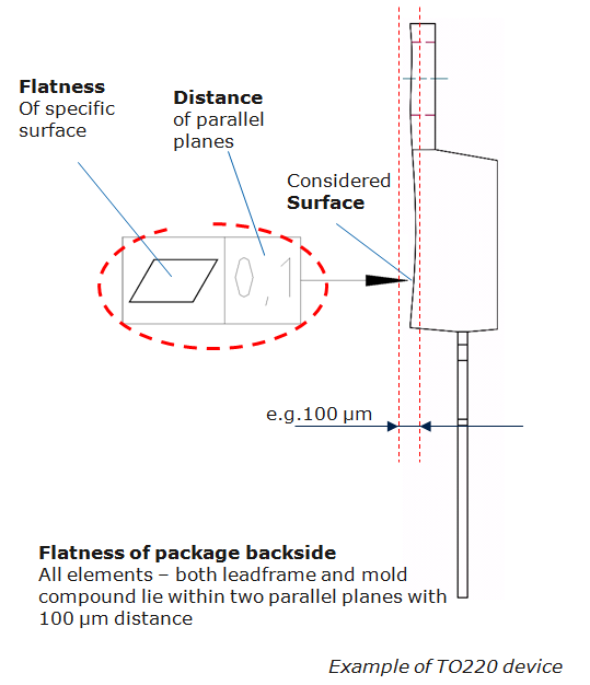
Figure 2.1 shows the TO-220 package curvature specifications.
Using precision laser scans, the flatness of the TO-220 package is assessed along a contour line at the center of the device. The analysis results confirm that the curvature values obtained from this study remain below the 100µm range.
Optical Package Scanning TO-247 (Figure 2.2)
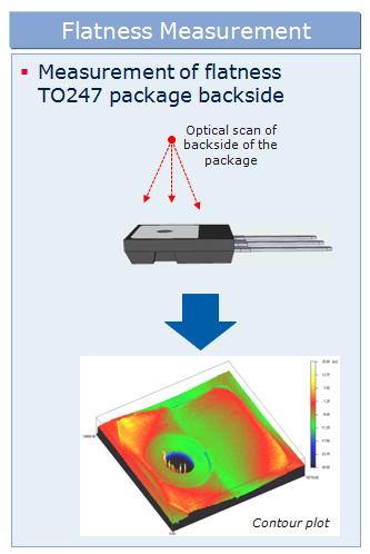
Figure 2.2 shows the outline of the package TO-247 after optical scanning. Flatness Assessment (Figure 2.3)
Figure 2.3 shows the flatness evaluation along the contour line in the center of the bundle.
Similar to the TO-220 package, the package TO-247 is optically scanned. The contour plot visually shows the flatness of the surface along the contour line in the center of the pack. The results confirm that the package TO-247 maintains curvature values well below the specified limit of 100µm.
Careful evaluation along the contour lines confirms that both the TO-220 and TO-247 < /a> exhibit curvature values below 20µm, well below the stringent specifications of 100µm.
Curvature Compliance Summary (Figure 2.4)
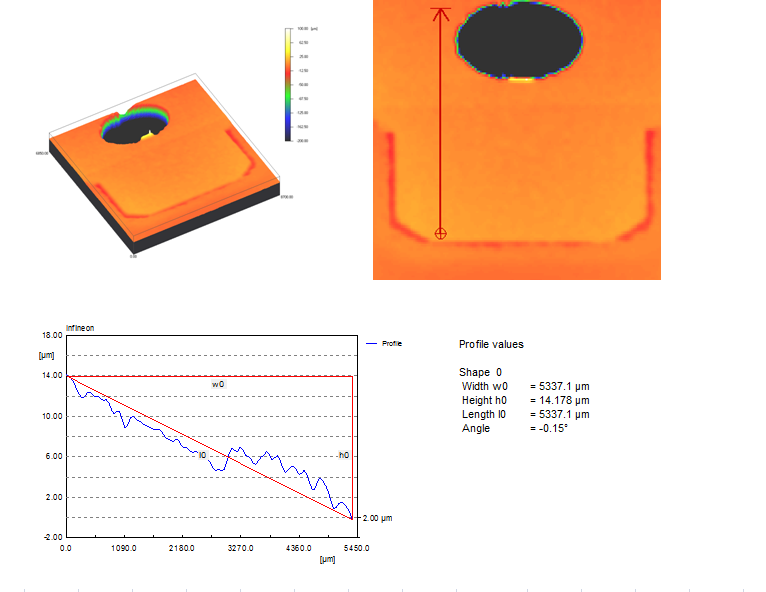
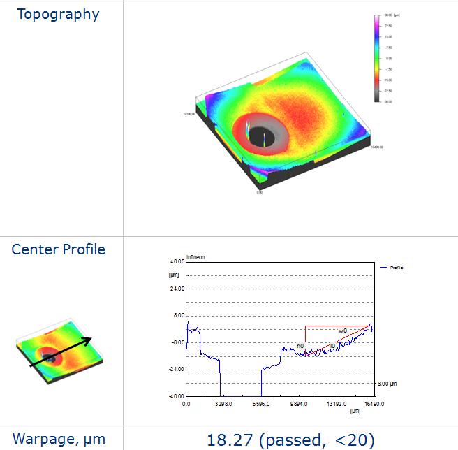
Figure 2.4 summarizes the curvature measurements from the contour line at the center of the TO-220 and TO-247 .
Height measurements from the contour lines indicate a maximum curvature of less than 20µm. Both TO-220 and packages TO-247 not only meets but also exceeds specifications , ensuring structural stability within specified limits.
In fact, optical scanning and contour plot evaluations confirm that the curvature dynamics of TO-220 packets and TO-247 is within the specified range, laying a solid foundation for further investigation of the effects of bolt torque on these carefully characterized devices.
Application of Screw Torque: Optimizing Manufacturing Processes for Increased Thermal Efficiency
In the complex semiconductor manufacturing landscape, applying torque to a screw is not just a mechanical step; is a critical optimization process that directly affects the thermal performance and durability of insulated gate bipolar-unipolar transistors (IGBTs). This piece delves into the subtleties of the manufacturing process, highlighting optimizations to minimize device curvature and emphasizing the importance of precise application of assembly torque.
Production Process Optimization
Connector Frame and Precision Molding
At the heart of the manufacturing process is a meticulous approach to the connector frame and molding. Rigorous optimization efforts are undertaken to ensure that device curvature is kept to an absolute minimum. By adjusting manufacturing parameters, the structural integrity of the IGBT is maintained, creating the basis for efficient heat dissipation.
Flatness Monitoring
Continuous flatness monitoring is integral to the manufacturing process. The contact between the IGBT package and the insulating film is the critical thermal conduction interface. Through vigilant control, flatness is carefully controlled, ensuring that contact areas remain as close to each other as possible, maximizing thermal conductivity.
The Importance of Correct Installation Torque
Maximizing Contact Areas
One of the key roles of screw torque is to maximize the contact areas between the IGBT pack and the heatsinks. As the torque increases, the contact pressure between these surfaces is amplified. This leads to increased thermal conductivity, creating efficient heat flow paths, crucial for maintaining optimal device temperatures.
Efficient Heat Dissipation
A key aspect of optimizing bolt torque is achieving effective heat dissipation. By precisely applying the appropriate torque, thermal resistance at the contact surfaces is minimized. This not only ensures efficient heat transfer, but also prevents air gaps that can hinder thermal conduction.
Finding Balance
Risk of Insufficient Moment
Using too low a torque carries the risk of increasing the thermal contact resistance. If there is insufficient pressure, the thermal contact between the pack and the heatsinks is compromised, leading to suboptimal heat dissipation.
Risk of Excessive Torque
In turn, excessive mounting torque may deform the pack head and mounting tab, potentially lifting the pack away from the heatsink. This deformation not only compromises thermal performance, but also increases the risk of mechanical damage to the IGBT.
Optimum Moment: Delicate Balance
So finding the optimal installation torque is a delicate balance. This requires applying sufficient torque to ensure minimal thermal resistance while avoiding the pitfalls of insufficient or excessive pressure.
In summary, applying screw torque is a key step in IGBT manufacturing. Manufactured with precision, it not only minimizes device curvature through meticulous process optimizations, but also provides efficient heat flow paths, ultimately increasing the thermal efficiency and reliability of discrete IGBTs.
Screw Mounting on a Heat Sink: Ensuring Precision and Stability in Thermal Conduction
In insulated gate bipolar-unipolar transistor (IGBT) assembly, the screw mounting process on the heat sink plays a key role in establishing a stable and efficient thermal path. This piece delves into the traditional bolt installation method, highlighting the importance of specific components such as rectangular washers. Additionally, we explore the advantages of using electric screwdrivers, providing better control and accuracy in the key step of tightening the screw.
Traditional Screw Installation Method
Components: Screw, Nut, Washer
The traditional approach to mounting a bolt to a heatsink involves using the basic components - a bolt, nut, and washer. These components work together to secure the IGBT device to the heatsink, creating the primary connection for heat conduction.
Rectangular Pad : Key Element
Rectangular washer , strategically placed between the bolt head and mounting tab, plays a key role in this process. Its design ensures even pressure distribution, preventing damage to the plastic body of the IGBT package housing during the assembly process. This small but critical component protects the structural integrity of the device while facilitating efficient heat conduction.
The role of electric screwdrivers
Precision and Control
As technology advances, the integration of electric screwdrivers is becoming a significant improvement on the traditional assembly method. Electric screwdrivers offer unparalleled precision and control when tightening a screw, ensuring that the specified torque is applied with even effectiveness.
High Repeatability of Tightening with Precision
Electric screwdrivers have high repeatability of tightening precision, contributing to the reliability and uniformity of the assembly process. This feature becomes particularly important in the context of IGBT assembly, where precise torque application is essential to optimize thermal conduction and prevent mechanical damage.
Variable Speed Control
One of the significant advantages of electric screwdrivers is their ability to adjust the variable speed. This feature allows operators to select the optimal screw tightening speed to suit the specific requirements of the IGBT assembly. The ability to adjust tightening speed adds an extra layer of control, eliminating the risk of over-tightening and ensuring a firm but secure connection.
Assembly Methods Illustrated
Correct Tightening Techniques
For a visual guide to proper installation techniques, see Figure 5.1. This illustration shows the recommended mounting methods for both TO-220 and TO-220FP packages. Paying attention to the placement of rectangular washers and using electric screwdrivers can significantly increase the precision and reliability of the entire screw assembly process on the heatsink. 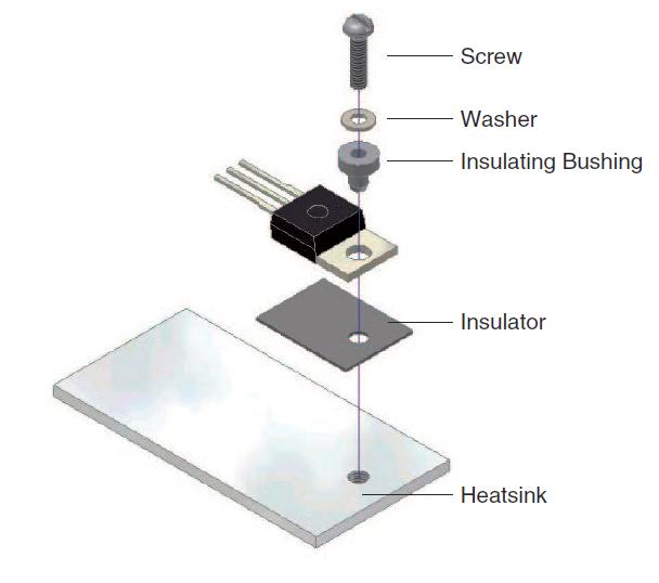
Figure 5.1: Installation methods for TO-220 and TO-220FP package
In summary, the process of mounting the screw on the heat sink is a fundamental step in IGBT assembly, forming the basis for efficient heat conduction. By integrating traditional components such as rectangular washers and modern tools such as electric screwdrivers, manufacturers can achieve a delicate balance of precision, stability, and control, which ultimately contributes to the increased performance and durability of discrete IGBTs.
The Importance of Flat Heatsink: Protecting Device Integrity Through Surface Precision
In the complex world of semiconductor assembly, heat sink flatness becomes a key factor, having a profound impact on the structural integrity and operational reliability of insulated gate bipolar-unipolar transistors (IGBTs). This piece delves into the importance of a flat heat sink, highlighting the risks associated with uneven surfaces and the potential for cracking of the device due to increased mechanical stress.
The Role of Radiators in Heat Management
Efficient Heat Dissipation
The heat sink plays the main role in dissipating heat generated during the operation of electronic devices, including IGBTs. A flat heat sink is essential to achieve maximum contact between the device package and the heat sink surface, allowing for optimal thermal conduction and efficient heat dissipation to the surroundings.
Risks of Uneven Radiator Surface
Mechanical Stress on Device
Inequalities in the heat sink surface pose a significant risk to the structural integrity of the IGBT. When the device is mounted on a heat sink with an irregular surface, it introduces mechanical stress in the screw hole area. This stress is magnified when torque is applied to the bolt, creating potential room for structural weaknesses.
Device Cracking: Effect of Mechanical Stress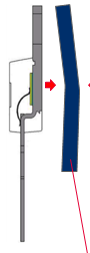
Figure 6.1: Illustration of a heat sink with an uneven surface
As shown in Figure 6.1, when the device is mounted on a heat sink with an uneven surface, high mechanical stress occurs in the screw hole area. This stress, over time, can lead to the device cracking, compromising its functionality and service life.
High Mechanical Stress on Mold Compound (Figure 6.2)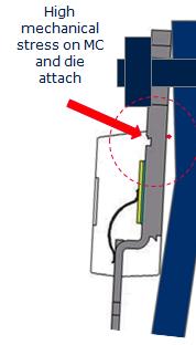
Figure 6.2: High mechanical stress on the mold compound when the device is mounted on a heat sink with an uneven surface
The graphical representation in Figure 6.2 visually highlights areas of high mechanical stress on the mold compound when the device is mounted on a heat sink surface with an uneven surface. The stress concentration near the screw hole highlights the risk of structural damage, emphasizing the criticality of a flat and even heat sink surface.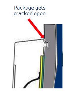
Cracking Device: Visual Effect (Figure 6.3)
Figure 6.3: Package cracked near screw hole due to high mechanical stress
Figure 6.3 illustrates the consequences of high mechanical stress, showing a cracked package near the bolt hole. This visual representation highlights the urgent need to maintain a flat heat sink surface to mitigate the risk of mechanical stress and subsequent cracking of the device.
Summary: Prioritize Flatness for Durability
In summary, the importance of a flat heat sink cannot be overstated in the world of IGBT assembly. The risks associated with surface irregularities, including increased mechanical stress and potential device breakage, highlight the critical need for precision in heatsink manufacturing. By prioritizing flatness, manufacturers contribute to the durability and reliability of discrete IGBTs, ensuring they operate seamlessly in a variety of electronics applications.
Incorrect Editing Examples: Revealing Real-World Consequences
The use of screw torque in the assembly of insulated gate bipolar-unipolar transistors (IGBTs) requires precision and attention. This piece explores real-life examples that vividly illustrate the serious consequences of incorrectly tightening a bolt. From damage and delamination to crystal cracks and surface dents, these cases highlight the critical importance of following recommended torque values to protect device integrity.
Example 1: Delamination of Form Union (Figure 7.1)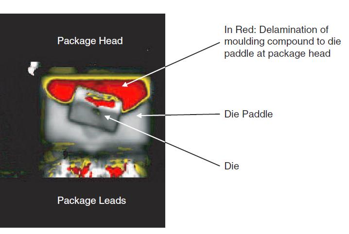
Figure 7.1: Delamination of form relationship from frame
In this example, Scanning Acoustic Microscopy (CSAM) reveals delamination of the mold compound from the frame caused by external mechanical stress caused by excessive screw torque. Separation of the mold compound from the frame compromises the structural integrity of the IGBT, leading to potential operational problems and reduced device life.
Example 2: Vertical Crystal Crack (Figure 7.2)
Figure 7.2: Cross-section showing a vertical crack in the crystal
Figure 7.2 illustrates a cross-section of a device with a vertical crystal crack caused by external mechanical stress resulting from incorrect screw tightening torque. This crack compromises IGBT functionality, potentially leading to performance degradation and increased failure rates.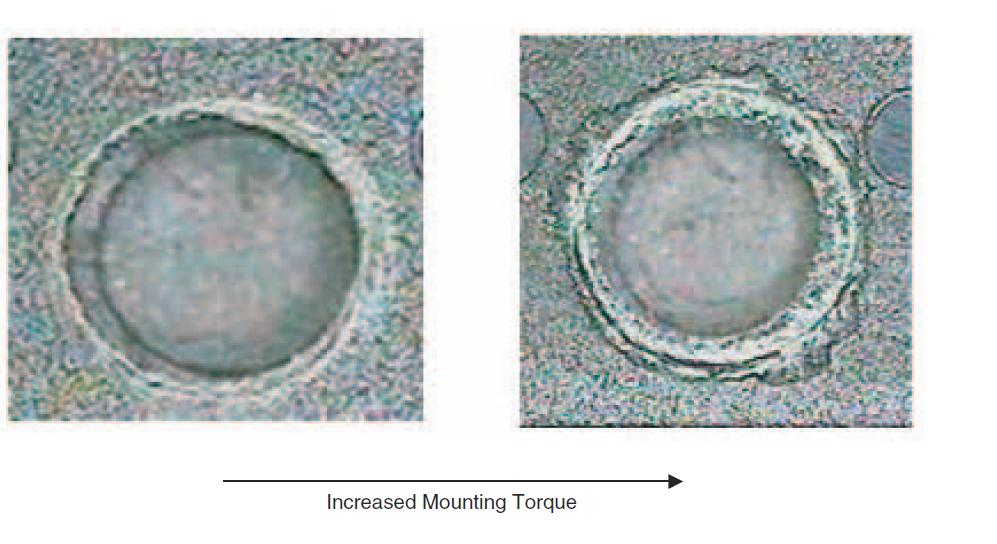
Example 3: Surface Dent (Figure 7.3)
Figure 7.3: Surface damage of mold compound
Surface dents, as shown in Figure 7.3, represent the effects of over-tightening. Excessive screw torque damages the surface of the mold compound, introducing weaknesses in the structural integrity of the device. Such dents can act as concentrated stress points, further increasing the risk of failure.
Example 4: Heatsink Penetration (Figure 7.4)
Figure 7.4: Heat sink penetration causing short circuit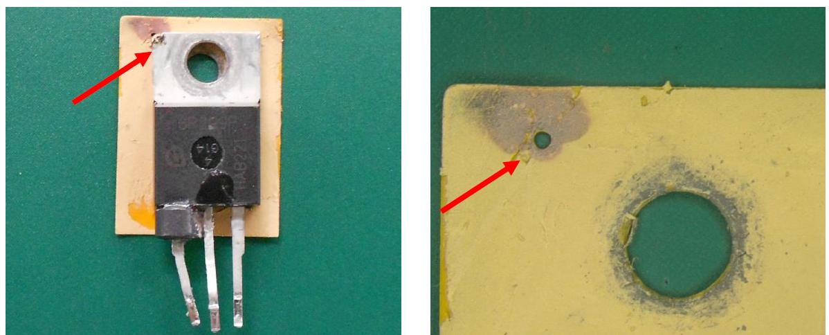
In this striking example, Figure 7.4 presents a damage analysis that reveals a sharp corner of the heat sink penetrating the insulating foil due to the high screw tightening torque. This cross-talk leads to a short between the heat sink and the device's drain, potentially leading to catastrophic failures.
Damage Catalog (Figure 7.5)
Figure 7.5: Catalog of device damage types
Summarizing the various types of damage caused by incorrect bolt torque, Figure 7.5 offers a comprehensive picture. From delamination to crystal cracks and surface dents, this catalog highlights the critical need for precision in torque application to avoid compromising the structural integrity and functionality of discrete IGBTs.
Summary: Minimizing Risk Through Precision
In summary, these real-life examples serve as warnings, illustrating the far-reaching consequences of incorrect bolt torque. Manufacturers and installers must attach importance to precision in the application of tightening torque to minimize the risk of damage, delamination, crystal cracks, and surface dents. By adhering to the recommended torque values, the industry can ensure the durability, reliability, and optimal performance of discrete IGBTs in a variety of electronics applications.
Tightening Torque and Rth(j-c) Value Study: Revealing Lessons Learned for Optimal Thermal Performance
This piece delves into a comprehensive study conducted to discover the complex relationships between tightening torque and thermal resistance (Rth(j-c)) values in various insulated bipolar-unipolar transistor packages gateway (IGBT). The study examines the effect of tightening torque on thermal performance, taking into account differences in package types, insulating films, and hardness factors.
Research Parameters and Device Portfolio (Table 8.1)
The study covers a variety of devices from Infineon's best-selling line, including single IGBT, DuoPackTM, and retrograde conduction variants. These devices, with different current classes and package types, such as TO-220, TO-247 and TOHC, constitute the basis of the study.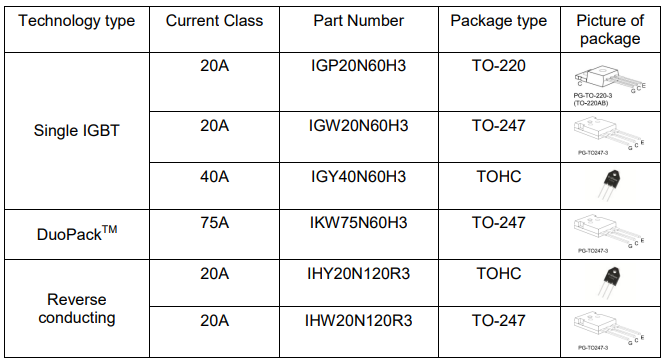
Table 8.1: Portfolio of devices used to test tightening torque and thermal resistance values
Insulation Foils and Hardness Factors (Table 8.2)
The study includes two different insulating foils: Keratherm86/82 and Keratherm70/50. These foils have different hardness factors, providing a comprehensive examination of their impact on thermal resistance values.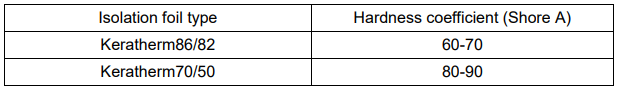
Table 8.2: Hardness coefficient of insulating films used in the test
Research Methodology (Figure 8.1)
Figure 8.1: Measurement device layout
The impact of various insulating foils on Rth(j-c) values was tested for devices assembled using a dry assembly technique, without the use of thermal paste. The devices were installed, and Rth(j-c) was measured in the screw tightening torque range from 0.4Nm to 1.2Nm.
Results and Conclusions
Impact on Keratherm86/82 Insulating Foil (Figure 9.1)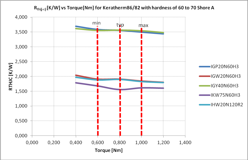
Figure 9.1: Rth(j-c) vs Screw tightening torque for Keratherm86/82 insulating foil with hardness factor 60-70 Shore A
The results indicate that devices using Keratherm86/82 (60-70 Shore A) insulating foil show minimal changes in Rth(j-c) values over the screw tightening torque range from 0 .6 to 1.0 Nm. The recommended screw tightening torque of 0.8 Nm is optimal for achieving thermal resistance stability.
Impact on Keratherm70/50 Insulating Foil (Figure 9.2)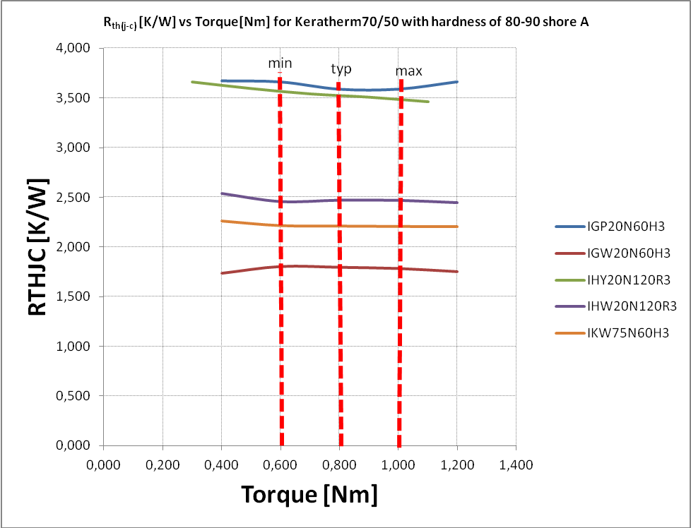
Figure 9.2: Rth(j-c) vs Screw tightening torque for Keratherm70/50 insulating foil with hardness factor 80-90 Shore A
Similarly, units using Keratherm70/50 (80-90 Shore A) insulating foil show consistent Rth(j-c) values over a bolt torque range of 0.6 to 1 .0Nm. A recommended screw tightening torque of 0.8 Nm is suggested to maintain thermal performance.
Analysis Summary (Figure 9.3)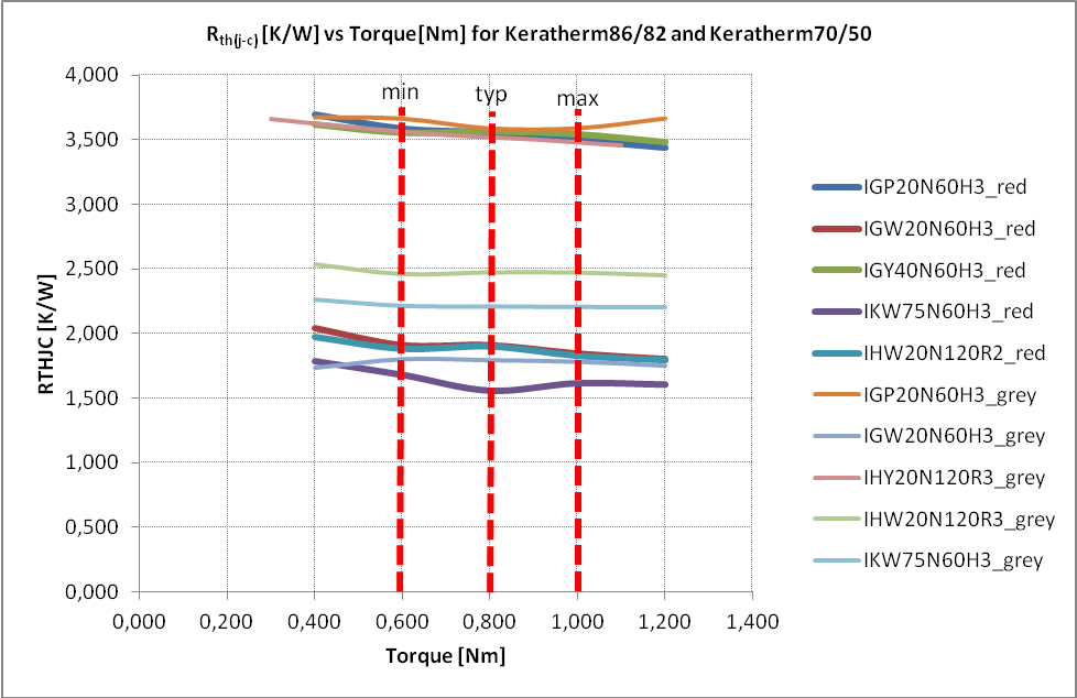
Figure 9.3: Rth(j-c) connection vs screw tightening torque for two types of insulating foils
The analysis summary, as shown in Figure 9.3, highlights that the thickness of the insulating film may change after the screw is applied, but the Rth(j-c) values remain stable over the screw tightening torque range from 0.6 to 1 Nm.
Recommendations for Application of Bolt Tightening Torque
Catalogue of types of device damage caused by excessive tightening torque of the screw on the device's heat sink
Based on the test results, a screw tightening torque range is recommended to prevent both mechanical damage to the device and to achieve optimal thermal resistance. This range is intended to strike a balance between applying sufficient tightening torque for optimal thermal contact, while avoiding excessive torque that could lead to damage to the device.
Summary: Precision for Optimal Performance
Investigating the application of screw torque in the context of Rth(j-c) values provides invaluable guidance in achieving optimal thermal performance in various insulated gate bipolar-unipolar transistor (IGBT) packages. By incorporating different package types, insulating films, and hardness factors, manufacturers can tailor torque application to specific device configurations, ensuring durability, reliability, and increased thermal conductivity in a variety of electronics applications.
Recommendation: Precise Tightening Torque for Optimum Thermal Performance
After a deep study of the complex relationships between screw tightening torque and thermal resistance (Rth(j-c)) values in various IGBT packages, insulating films, and hardness factors, a carefully considered recommendation emerges. This section presents the recommended screw tightening torque range to achieve optimal thermal contact while minimizing the risk of mechanical damage.
Recommended Tightening Torque Range: 0.6 to 1.0 Nm
The comprehensive study, as detailed in the previous sections, provided valuable information on the effects of tightening torque on the thermal performance of discrete IGBT devices. Based on the observed stability of the Rth(j-c) value in the screw tightening torque range from 0.6 to 1.0 Nm, this range is recommended for practical use.
Balance Thermal Contact and Mechanical Integrity
The recommended screw torque range achieves a delicate balance, ensuring that contact between the device package and the heatsink is optimized for thermal conduction. At the same time, it protects against potential mechanical damage, in accordance with industry standards and best practices.
Damage Prevention: A Holistic Approach
Catalogue of types of device damage caused by excessive tightening torque of the screw on the device's heat sink
Referring to the recommended bolt tightening torque range, it acts as a preventive measure against the catalog of damages resulting from excessive bolt tightening torque. By staying within the 0.6 to 1.0 Nm range, manufacturers can reduce the risk of delamination, die cracks, surface dents, and other structural sensitivities, ensuring the durability and reliability of IGBT devices.
Customization for Specific Configurations
While the recommended bolt torque range is a general guideline, it is important to recognize that differences in device configurations, insulating films, and package types may require minor adjustments. Manufacturers are encouraged to consider specific parameters of their IGBT assembly to fine-tune torque application for optimal performance.
Summary: Precision for Optimal Performance
This comprehensive exploration of the relationship between screw tightening torque and thermal resistance values in various IGBT packages underscores the critical importance of precision in assembly. By applying the recommended tightening torque range of 0.6 to 1.0 Nm, manufacturers can achieve the delicate balance between thermal performance and mechanical integrity, ensuring the durability, reliability, and optimal functionality of discrete IGBT devices across diverse applications.
Key Takeaways:
1. The flatness of the heat sink is crucial for optimal thermal contact between the device package and the heat sink surface.
2. Uneven heat sink surfaces can lead to increased mechanical stress on the device, potentially causing cracking and reduced device life.
3. Precision in applying screw tightening torque is essential to achieve a balance between thermal performance and mechanical integrity.
4. Following recommended torque values helps prevent damage such as delamination, crystal cracks, and surface dents, ensuring the long-term reliability of IGBT devices.
5. Customizing torque application based on specific device configurations and package types can further optimize thermal performance and reliability.
Conclusion:
Achieving optimal thermal performance and mechanical integrity in insulated gate bipolar-unipolar transistor (IGBT) assemblies requires careful attention to detail. By prioritizing flatness in heat sink manufacturing and adhering to recommended screw tightening torque values, manufacturers can mitigate the risk of mechanical damage and ensure the long-term reliability of IGBT devices across diverse applications.
Related posts
Now available – DC/DC converters from PREMIUM
We introduced a novelty to our permanent offer in DACPOL in the category of power supplies and converters and today...
Read more
New release in DACPOL lighting for lathes – Kira covers
We introduce a new product into the DACPOL category of industrial lighting and today we offer KIRA covers for...
Read more
Leave a comment