Configurable Current Transducer up to 100A AC/DC V4IA100A 24-240V AC/DC
  • Configurable Current Transducer up to 100A AC/DC V4IA100A 24-240V AC/DC

Photos are for informational purposes only. View product specification

please use latin characters

Manufacturer: TELE Haase

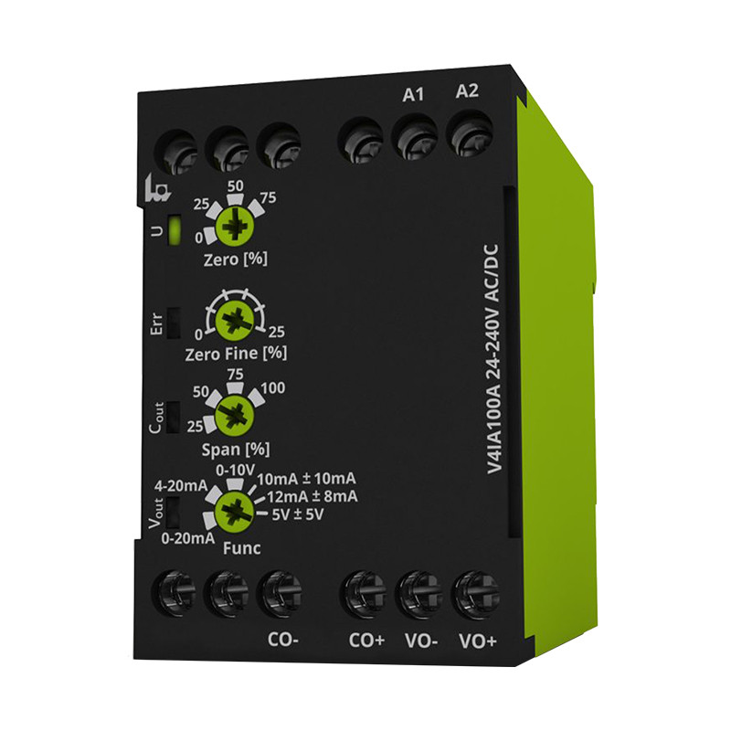
Configurable current transducer up to 100A AC / DC V4IA100A 24-240V AC / DC

Configurable Current Transducer up to 100A AC/DC V4IA100A 24-240V AC/DC

Description
The V4IA100A is a current transducer that allows direct measurement of direct and alternating current up to 100A. The device has several input ranges (25A, 50A, 75A and 100A) and can be supplied with different voltage levels (24-240V AC/DC). An important advantage is the possibility of bi-directional measurement, dedicated for applications related to energy storage.

Advantages
  • Galvanic isolation of the transmitter circuits
  • Direct current measurement up to ± 100A AC and DC
  • Selectable measuring range
  • Wide range of supply voltage (24-240V AC/DC)
  • The choice of output signal
  • Compact size (45mm) and DIN rail mounting

Application
  • Battery energy storage
  • Guaranteed power supply systems
  • Peak power systems


Technical Data


Power circuit
Terminals A1-A2
Supply voltage 48-240VAC (-10/+10%)
24-240VDC (-15/+20%)
Nominal frequency 16,6 … 400 Hz lub DC
Tolerance 16 … 420 Hz
Nominal load 230 V AC @ 50 Hz typ. 0,65 W / 1,2 VA
24 V DC typ. 0,55 W
Work cycle 100%
Power decay time < 6ms
Resume time ≥ 400 ms @ 24 V DC
Measurement circuit
Clamps Built into the transducer
Measured variable Single phase current
Measurement method TRMS
Measuring range 100 A AC/DC
Frequency     Sinusoidal signal: 16,6…400 Hz
  Non-Sinusoidal signal: 50/60 Hz


Available functions
Zero Setting the point 0:
0%, 25%, 50%, 75% of the rated value
Zero Fine Setting the exact point 0:
0…25% of the rated value
Span Span of measurement:
25%, 50%, 75%, 100% of the rated value
Analog output 0 ... 20 mA, 4 ... 20 mA, 0 ... 10 V
10 mA ±10 mA*, 12 mA ±8 mA*, 5 V ±5 V*
Status indicator
Green LED U - continuous illumination Indication of the presence of supply voltage
Yellow LED C - continuous illumination Analogue output 4 (0) ... 20 mA, 10 mA ±10 mA, 12 mA ±8 mA active
Yellow LED V - continuous illumination Analogue output 0 … 10 V, 5V ± 5V active
Red LED Err - continuous illumination Indicates an error has occurred


Output circuit (current)
Terminals CO+; CO-
Kind of output 4 … 20mA
0 … 20mA
10mA ± 10mA
12mA ± 8mA
Step response (0->100A) Typ. 130 ms (90% of the final value)
Settling time < 200 ms (99% of the final value)
Load 0 … 300 Ω
Galvanic isolation Between power supply, output and measuring circuit
Output circuit (voltage)
Terminals VO+; VO-
Kind of output 0 … 10V
5V ± 5V
Step response (0->100A) Typ. 130 ms (90% of the final value)
Settling time < 200 ms (99% of the final value)
Load 0 … 1,5 kΩ
Galvanic isolation Between power supply, output and measuring circuit


Accuracy
Base accuracy DC, AC Sinus
50/60 Hz
< 2 % typ. 0,5 %
AC Sinus
16,6 … 400 Hz
< 2,5 % typ. 0,5 %
CF < 2,8 @ 50 Hz
I peak max = 160A
< 4 %
Setting accuracy < 5 % (of full scale of „Zero Fine“potentiometer)
Repeat accuracy < 1 % typ. 0,1 %
Temperature influence < 0,05 % per °C
Damp influence +3 % of base accuracy (> 85% relative humidity)
Environmental conditions
Operation temperature -25 … +60°C
Storage temperature -40 … +70°C
Relative humidity 5 … 95 % (non-condensing)
Vibration 2 … 13,2 Hz: 1 mm; 13,2 … 100 Hz: 7 m/s2 (GL VI-7-2 category C)
Shock 150m/s2 11ms (IEC 60068-2-27)
Installation altitude up to 2000 m above sea level


General data
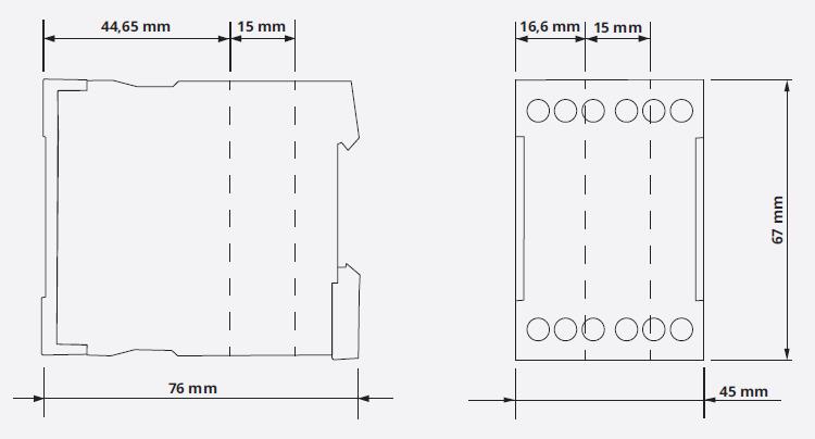
Dimensions 45x67x76 mm
Φ 15 mm
Mounting DIN rail (EN60715)
Mounting position any
Housing material PA 66, self-extinguishing plastic, class V-0
Degree of protection housing: IP40
terminals: IP20
Electrical connection Screw terminal
Wire size flexible with wire end ferrule:
0.5…2.5mm2 (20AWG…13AWG)
flexible without wire end ferrule:
0.5…4mm2 (20AWG…12AWG)
rigid:
0.5…4mm2 (20AWG…12AWG)
Stripping length 8 mm
Tightening torque max. 1Nm
Weight 147 g
Isolation data
Pollution degree 2
Overvoltage category II (III for measuring circuit with phase-to-neutral voltages ≤300 Veff)
Rated insulation voltage supply circuit/output circuit 300 V
measuring circuit/output circuit 550 V
supply circuit/measuring circuit 550 V
Rated impulse withstanding voltage supply circuit/output circuit 4 kV
measuring circuit/output circuit 6,4 kV
supply circuit/measuring circuit 6,4 kV
Degree of protection supply circuit/output circuit protective separation
measuring circuit/output circuit protective separation
supply circuit/measuring circuit protective separation


Connections


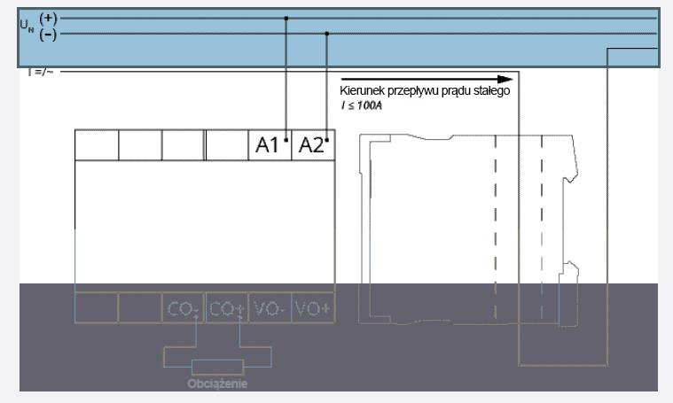
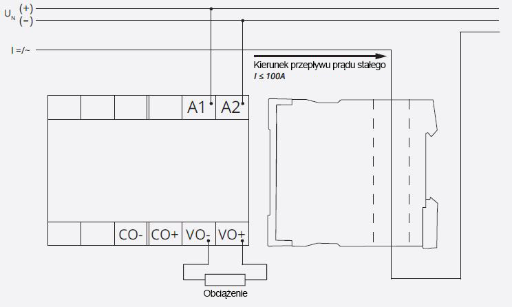
Output: 4..20mA, 0..20mA, 12mA+/-8mA, 10mA +/-10mA


Output: 0..10Vdc, 5V +/-5Vdc


Dimensions


Send an inquiry

Are you interested in this product? Do you need additional information or individual pricing?

Contact us

ASK FOR THE PRODUCT close
Message sent successfully.
ASK FOR THE PRODUCT close
Browse

Add to Wishlist

You must be logged in

Configurable Current Transducer up to 100A AC/DC V4IA100A 24-240V AC/DC

Description
The V4IA100A is a current transducer that allows direct measurement of direct and alternating current up to 100A. The device has several input ranges (25A, 50A, 75A and 100A) and can be supplied with different voltage levels (24-240V AC/DC). An important advantage is the possibility of bi-directional measurement, dedicated for applications related to energy storage.

Advantages
  • Galvanic isolation of the transmitter circuits
  • Direct current measurement up to ± 100A AC and DC
  • Selectable measuring range
  • Wide range of supply voltage (24-240V AC/DC)
  • The choice of output signal
  • Compact size (45mm) and DIN rail mounting

Application
  • Battery energy storage
  • Guaranteed power supply systems
  • Peak power systems


Technical Data


Power circuit
Terminals A1-A2
Supply voltage 48-240VAC (-10/+10%)
24-240VDC (-15/+20%)
Nominal frequency 16,6 … 400 Hz lub DC
Tolerance 16 … 420 Hz
Nominal load 230 V AC @ 50 Hz typ. 0,65 W / 1,2 VA
24 V DC typ. 0,55 W
Work cycle 100%
Power decay time < 6ms
Resume time ≥ 400 ms @ 24 V DC
Measurement circuit
Clamps Built into the transducer
Measured variable Single phase current
Measurement method TRMS
Measuring range 100 A AC/DC
Frequency     Sinusoidal signal: 16,6…400 Hz
  Non-Sinusoidal signal: 50/60 Hz


Available functions
Zero Setting the point 0:
0%, 25%, 50%, 75% of the rated value
Zero Fine Setting the exact point 0:
0…25% of the rated value
Span Span of measurement:
25%, 50%, 75%, 100% of the rated value
Analog output 0 ... 20 mA, 4 ... 20 mA, 0 ... 10 V
10 mA ±10 mA*, 12 mA ±8 mA*, 5 V ±5 V*
Status indicator
Green LED U - continuous illumination Indication of the presence of supply voltage
Yellow LED C - continuous illumination Analogue output 4 (0) ... 20 mA, 10 mA ±10 mA, 12 mA ±8 mA active
Yellow LED V - continuous illumination Analogue output 0 … 10 V, 5V ± 5V active
Red LED Err - continuous illumination Indicates an error has occurred


Output circuit (current)
Terminals CO+; CO-
Kind of output 4 … 20mA
0 … 20mA
10mA ± 10mA
12mA ± 8mA
Step response (0->100A) Typ. 130 ms (90% of the final value)
Settling time < 200 ms (99% of the final value)
Load 0 … 300 Ω
Galvanic isolation Between power supply, output and measuring circuit
Output circuit (voltage)
Terminals VO+; VO-
Kind of output 0 … 10V
5V ± 5V
Step response (0->100A) Typ. 130 ms (90% of the final value)
Settling time < 200 ms (99% of the final value)
Load 0 … 1,5 kΩ
Galvanic isolation Between power supply, output and measuring circuit


Accuracy
Base accuracy DC, AC Sinus
50/60 Hz
< 2 % typ. 0,5 %
AC Sinus
16,6 … 400 Hz
< 2,5 % typ. 0,5 %
CF < 2,8 @ 50 Hz
I peak max = 160A
< 4 %
Setting accuracy < 5 % (of full scale of „Zero Fine“potentiometer)
Repeat accuracy < 1 % typ. 0,1 %
Temperature influence < 0,05 % per °C
Damp influence +3 % of base accuracy (> 85% relative humidity)
Environmental conditions
Operation temperature -25 … +60°C
Storage temperature -40 … +70°C
Relative humidity 5 … 95 % (non-condensing)
Vibration 2 … 13,2 Hz: 1 mm; 13,2 … 100 Hz: 7 m/s2 (GL VI-7-2 category C)
Shock 150m/s2 11ms (IEC 60068-2-27)
Installation altitude up to 2000 m above sea level


General data
Dimensions 45x67x76 mm
Φ 15 mm
Mounting DIN rail (EN60715)
Mounting position any
Housing material PA 66, self-extinguishing plastic, class V-0
Degree of protection housing: IP40
terminals: IP20
Electrical connection Screw terminal
Wire size flexible with wire end ferrule:
0.5…2.5mm2 (20AWG…13AWG)
flexible without wire end ferrule:
0.5…4mm2 (20AWG…12AWG)
rigid:
0.5…4mm2 (20AWG…12AWG)
Stripping length 8 mm
Tightening torque max. 1Nm
Weight 147 g
Isolation data
Pollution degree 2
Overvoltage category II (III for measuring circuit with phase-to-neutral voltages ≤300 Veff)
Rated insulation voltage supply circuit/output circuit 300 V
measuring circuit/output circuit 550 V
supply circuit/measuring circuit 550 V
Rated impulse withstanding voltage supply circuit/output circuit 4 kV
measuring circuit/output circuit 6,4 kV
supply circuit/measuring circuit 6,4 kV
Degree of protection supply circuit/output circuit protective separation
measuring circuit/output circuit protective separation
supply circuit/measuring circuit protective separation


Connections


Output: 4..20mA, 0..20mA, 12mA+/-8mA, 10mA +/-10mA


Output: 0..10Vdc, 5V +/-5Vdc


Dimensions