Main features:
- Dimensions: 180x230x66 mm
- Room cooling fan control
- On-Off control
- Has six relay outputs for cooling, defrosting, fan, lighting, alarm, and auxiliary control (AUX)
- Three NTC probe inputs for cooling, defrosting, and optional indicator
- Total two digital inputs, adjustable by door control and parameter
- Offset settings that can be entered for NTC probe inputs
- Compressor protection function with parameter
- Compressor start, stop, or cycling function in the event of probe failure
- Smart defrost function selectable
- Manual quick start function Cooling
- Manual or time- and temperature-dependent defrosting
- Adjustable lower and upper setpoint limits
- Adjustable defrost time and interval
- Adjustable lower and upper alarm limits depending on the set value
- Display of temperature units in °F and °C
- Communication function via RS485 ModBus RTU protocol
- Option to edit and transfer parameters via NFC (optional)
- CE marking according to EN standards
Connection and terminal diagram:

Translation:
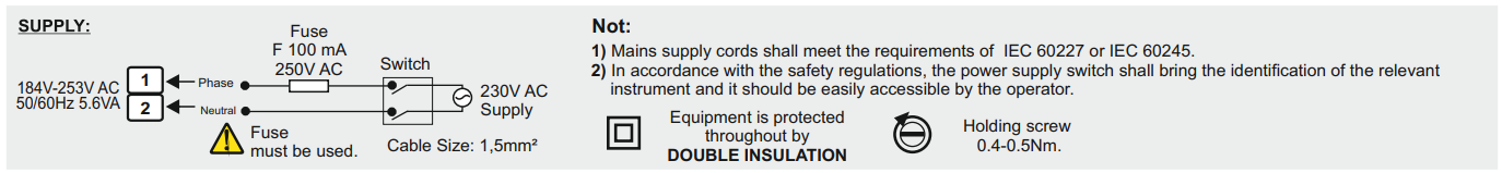
- SUPPLY -> POWER SUPPLY
- Fuse -> Fuse
- Fuse must be used. -> Fuse must be used.
- Switch -> Switch
- Cable size -> Wire size
- Note -> Note
- Mains supply cords shall meet the requirements of IEC 60227 or IEC 60245 -> Power cables should meet the requirements of IEC 60227 or IEC 60245.
- In accordance with the safety regulations, the power supply switch shall bring the identification of the relevant instrument and it should be easily accessible by the operator. -> In accordance with safety regulations, the power switch should be marked with the appropriate device and should be easily accessible to the operator.
Technical Data
| Parameter |
Value |
| Electrical Parameters |
|
| Power Supply Voltage |
230V AC 50/60Hz |
| Maximum Power Consumption |
5.6VA |
| Connection |
2.5 i 1.75mm2 screw terminals |
| Range |
-60…150°C |
| Display |
120x70mm, 3 digits and single dot at the top, 4 digits and double dots at the bottom (minus sign at the top), 9 notification LEDs. |
| Outputs |
|
| Compressor relay output |
For resistive load: NO 277V AC 20A,
for inductive load: 2hp 250V AC
Relay life: No load 10,000,000 Switching cycles, 277V AC 20A for resistive load 100,000 switching cycles |
| Defrost relay output |
For resistive load: NO 250V AC 16A, NC 250V AC 16A,
for inductive load: 1/2hp 240V AC
Relay life: No load 30,000,000 switching cycles, 250V AC, 16A for resistive load 100,000 switching cycles |
| Fan relay output |
For resistive load: NO 250V AC 16A,
for inductive load: 1/2hp 240V AC
Relay life: No load 30,000,000 switching cycles, 250V AC, 16A for resistive load 100,000 switching cycles |
| Lighting relay output |
For resistive load: NO 250V AC 16A,
for inductive load: 1/2hp 240V AC
Relay life: No load 30,000,000 switching cycles, 250V AC, 16A for resistive load 100,000 switching cycles |
| Alarm relay output |
For resistive load: NO 250V AC 8A, NC 250V AC 8A
for inductive load: 1/2hp 240V AC
Relay life: No load 30,000,000 switching cycles, 250V AC, 8A for resistive load 100,000 switching cycles |
| Auxiliary relay output (AUX) |
For resistive load: NO 277V AC 20A,
for inductive load: 2hp 250V AC
Relay life: No load 10,000,000 switching cycles, 277V AC 20A for resistive load 100,000 Switches |
| Control |
|
| Control Type |
Compressor, Defrost, Fan, Light, Alarm, and Auxiliary Output Control with Setpoints and Digital Inputs |
| Control Algorithm |
On/Off |
| Hysteresis |
Adjustable 1…20°C |
| Environmental Conditions |
|
| Temperature Ambient/Storage |
0…+50°C/-25…70°C (no icing) |
| Protection class |
IP65 according to EN 60529 |
| Housing |
|
| Housing type |
Wall mounting |
| Dimensions (height x width x depth) |
180x230x66mm |
| Weight |
approx. 1150g (packed) |
| Housing material |
Self-extinguishing plastics are used |
Dimensions and assembly

To mount the device:
1) Unscrew the screws in step 1 and remove the front cover.
2) It should be mounted on the wall at the points marked 2.
3) The electrical connection should be made in accordance with the wiring diagram.
4) The cover should be closed and the removed screws tightened.
Note: if the cable exits are to be from the top, the rear cover with the cable exits facing upwards can be mounted on the wall. The rear cover has three marked spots at the top and bottom that need to be drilled to allow the cables to pass through.
Indicator LED and Button Descriptions
| LED |
Description |
 |
- When lit, the control is disabled. |
 |
- When lit, the compressor is running
- When flashing, the start delay is active |
 |
- When lit, defrosting is running
- When flashing, the start delay is active |
 |
- When lit, the fan is running
- When flashing, the start delay is active |
 |
- When lit, the lighting is on |
 |
- When lit in "Operation Mode", the alarm is active
- when lit in "Programming Mode", it indicates that the parameter has been transferred to the user menu. |
 |
- when lit, the auxiliary output is active. |
 |
Temperature unit indicator diodes, the active diode indicates the appropriate Unit |
| Button |
Description |
 |
- in "Operation Mode" change the setpoint temperature, reset the minimum and maximum measured temperature values (after reset, they are equal to the currently measured temperature)
- in "Programming Mode" change the value of the selected parameter |
 |
- in "Operation Mode," displays the maximum value of the measured temperature, turns off the audible warning.
- in "Programming Mode," used to increase the value of the selected parameter. |
 |
- in "Operation Mode," displays the minimum value of the measured temperature.
- in "Programming Mode," used to decrease the value of the selected parameter. |
 |
Used to stop control by closing the appropriate device outputs. |
 |
Starts and stops manual rapid cooling. |
 |
Starts and stops manual defrosting |
 |
Turns the lighting on and off |
 |
Activates and deactivates the auxiliary output |
C.SE (Cooling Set) Displaying and changing the set temperature value:

Translation:
Operating Mode -> Operating Mode
Main Display -> Main Display
In "Operating Mode", the measured temperature value is displayed on the upper screen, while the set value is displayed on the lower screen. When the  button is pressed, the setpoint value on the lower screen starts flashing and can be changed using the
 buttons. Then, if the
  button is pressed again, the set value is saved and the device returns to "Operation Mode".
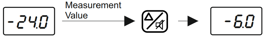
Checking the minimum value of the measured temperature
Translation: Measurement Value -> Measurement value
Pressing the  button in "Operation Mode" will display the lowest temperature measured (at all times) on the lower screen for 3 seconds.
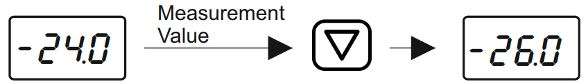
Checking the maximum measured temperature.
Translation: Measurement Value -> Measurement Value
Pressing the button in "Operation Mode" will display the highest measured temperature (at all times) on the lower screen for 3 seconds.
Resetting the minimum and maximum measured temperature values

Translation: Measurement Value -> Measurement value
In "Operation Mode", pressing the button for 7 seconds will reset the minimum and maximum values of the measured temperature, and their values will be changed to the value of the currently measured temperature. A message will appear on the lower screen.
Locking and unlocking buttons
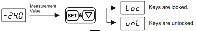
Translation:
Measurement Value -> Measurement Value
Keys are locked -> The buttons are locked.
Keys are unlocked -> The buttons are unlocked.
In "Operation Mode", first hold down the button, then press the button and hold both for 2 seconds. After this time, a message will be displayed and the buttons will be locked. If the same operation is performed when the buttons are locked, a message will appear on the screen and the buttons will be unlocked. If any button is pressed while the buttons are locked, a message will be displayed and no action will be performed.
Activating/Deactivating Control Outputs
In "Operation Mode", hold the button for 2 seconds. After this time, only the  LED will be displayed on the screen, and the control outputs will become inactive. When the control outputs are disabled, pressing the button for 2 seconds will cause the LED to turn off and the device will continue to control. When the control is off, the AUX backlight and its output status are maintained, and the relay state can be changed.
Manual Fast Cooling
In "Operating Mode", if the device is not defrosting and the outputs are not disabled, press the button for 2 seconds. If the button is pressed during the fast cooling process, it starts or stops it. The compressor operates for the time  . If the parameter is set to 0, manual rapid cooling is not performed.
Manual Defrost
In "Operation Mode", if the outputs are not off, press the button for 2 seconds. If pressed during a manual defrost operation, the operation is started or stopped. Defrosting lasts as long as the dti indicates. If the dti parameter is equal to 0, defrosting is not performed.
Lighting output activation/deactivation
In "Operation Mode", pressing the  button for 2 seconds will activate or deactivate the lighting output.
Auxiliary output (AUX) activation/deactivation
In "Operation Mode", pressing the  for 2 seconds will activate or deactivate the AUX auxiliary output.
Disabling the audible signal and alarm output
In the event of an alarm, the alarm relay is activated along with the audible signal. Pressing the button will deactivate the audible signal. Depending on the state of the parameter  the alarm relay may remain active until the alarm disappears or the alarm output may be deactivated.
If the sound when pressing the buttons is to be completely turned off, in "Operation Mode", hold down the button, then additionally press the button and hold both together for 4 seconds. A message will appear on the lower screen and the sound when pressing will be turned off. If you use the same combination to re-enable the sounds, the message  will be displayed, and the button press sound will be enabled.
Door Digital Input
1. Door Digital Input: When the door is opened, the alarm output is activated when the digital input delay time expires. The other outputs are activated or deactivated, depending on the parameter. The message
 is displayed.
2. Configurable digital input: When a signal is present at the input, the digital input becomes active after the digital input delay time has elapsed. The associated outputs are switched on or off depending on the  parameter. The appropriate message is displayed according to the status on the display.
Auxiliary output (AUX)
The auxiliary output can be used in 4 different ways, depending on the parameter:
1) Set to  : the auxiliary output is inactive
2) Set to  : the auxiliary output can be activated or deactivated only by pressing the AUX button on the front panel without any control
3) Set to  : the output is activated when the device is turned on and deactivated when it is turned off
4) Set to  : the device performs a second temperature check and the auxiliary output is activated or deactivated. For this check to be performed correctly, pay attention to 5 parameters:
 .
.
Restoring factory settings
Pressing the buttonfor 6 seconds after entering the menu and setting the security parameter to , the message
  will be displayed on the lower display and the device will be reset to factory settings.
Displaying the version number
In "Operation Mode", pressing the  and The lower screen will display the following information: software code, year, and month/day:
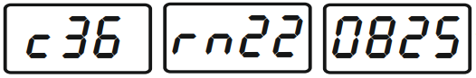 .
.
Definitions of errors, warnings, and alarms
| Message |
Description |
 |
Thermostat probe malfunction. Check the sensor connection. The alarm output is active, the compressor output is operating according to parameters. Other outputs remain unchanged. |
 |
Defrost probe malfunction. Check the sensor connection. The alarm output is active. Other outputs remain unchanged. |
 |
Indicator probe malfunction. Check the sensor connection. The alarm output is active. Other outputs remain unchanged. |
 |
Upper temperature limit alarm. Check system operation. The alarm output is active. Other outputs remain unchanged. |
 |
Low temperature limit alarm. Check system operation. The alarm output is active. Other outputs remain unchanged. |
 |
Indicates that the password is incorrect. Check the password. The outputs remain unchanged. |
|
Indicates that an external alarm has occurred. Check system operation. The alarm output is active. Other outputs remain unchanged. |
 |
Indicates that a serious external alarm has occurred. Check system operation. The alarm output is active. The remaining outputs are disabled. |
 |
An open door indicates an alarm. Check system operation. The alarm output is active. The state of the remaining outputs varies depending on the  parameter. parameter. |
Device programming

Translation:
Operating Mode -> Operating Mode
Main Display -> Main Display
Press and hold the upper button and then press the lower button for 2 seconds.
If kept pressed, the menu selecton screen is displayed. -> Press and hold the upper button, then press the lower button for 2 seconds. After this time, the menu selection screen is displayed.
No button is pressed for 30 seconds or the AUX button for 2 seconds. If kept pressed, it returns to operating mode. -> No button is pressed for 30 seconds or the AUX button is held for 2 seconds, after which the device returns to operating mode.
If no key is pressed for 3 seconds, the parameter selecton menu is returned. -> If no button is pressed for 3 seconds, you will return to the parameter selection menu.
password
 menu is entered _> Entering the menu
The device has two menus:  and . Menu has the following parameters by default:
  . Menu has all the device parameters. To access the menuyou must enter the password "-19" in the security parameter
 . The user can transfer parameters from the menu to the menu at his/her discretion. To move a parameter from the menu to the menu , find the appropriate parameter in the menu and then press . This will cause the
  LED to light up and the parameter to be entered into the menu. To remove a parameter from the menu, find this parameter in the menu and then press the button, which will delete the parameter and only the LED. Uwaga: przy każdym parametrze w menu , który znajduje się również w menu , świeci dioda . Po listę wszystkich parametrów oraz mapę adresową odsyłamy do noty katalogowej.


