Main features:
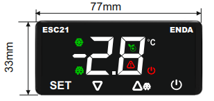
- Dimensions: 77 x 33 x 41 mm with touch buttons.
- 1 relay output for cooling or heating control.
- 1 NTC input and 1 digital input.
- Digital input can be used as a second NTC input.
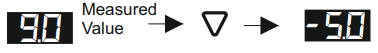
- An offset value can be entered for the NTC input.
- Compressor control, energy saving, or door alarm via the digital input.
- Delay time and minimum run time settings to protect the compressor.
- Defrost duration and interval settings.
- Defrost function dependent on time or evaporator temperature, or controlled by manually.
- Smart defrost option selectable.
- The upper and lower setpoint limits can be adjusted.
- Lower limit, upper limit, and alarm delay settings.
- Energy saving mode activation via digital input.
- Temperature unit in °C or °F.
- CE marked according to EN standards.
Technical Data:
| Parameter |
Value |
| Electrical Parameters |
| Power Supply Voltage |
230V AC 50/60Hz |
| Maximum Power Consumption |
0.65VA |
| Connection |
Screw Connector 2.5mm2 |
| Maximum sensor wire resistance |
100Ω |
| Analog input measurement range |
NTC resistance sensor -60…+99°C |
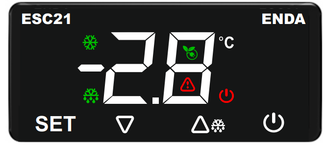
| Display |
2 digits, 37mm, 7-segment, with 7 function icons |
| Output |
| Compressor control output |
Resistive load: NO 250V AC 16A, NC 250V AC 16A
Inductive load: 1/2 HP 240V AC |
| Relay life |
Mechanical 30,000,000; Electrical 300,000 operations. 250 V AC, 16 A (resistive load) |
| Control |
| Control Format |
Single Setpoint, Door and Alarm Control |
| Control Type |
On-Off |
| Hysteresis |
Adjustable from 0.1 to 20.0 °C |
| Environmental Conditions |
| Temperature Ambient/Storage Temperature |
0…+50°C/-25…70°C (no icing) |
| Protection Rating |
According to EN 60529; Front panel: IP65, rear panel: IP20 |
| Housing |
| Housing type |
Suitable for flush mounting (according to DIN 43 700) |
| Dimensions (width x height x depth) |
77x33x41mm |
| Weight |
90g (packed) |
| Housing material |
Self-extinguishing plastics artificial |
Connection diagram:


Translation:
NOTE
SUPPLY
Fuse
Line
Neutral
Fuse should be connected. – The fuse should be connected.
Switch – Switch
Cable size – Wire size
Mains supply cords shall meet the requirements of IEC 60227 or IEC 60245. - Power cords should meet the requirements of IEC 60227 or IEC 60245.
In accordance with the safety regulations, the power supply switch shall provide the identification of the relevant instrument and it should be easily accessible by the operator. - In accordance with safety regulations, the power switch should be marked with the appropriate device and should be easily accessible to the operator.
Mounting:
To remove the mounting clips:
- Press the flush-mounting clip in the direction shown in the figure below. Then pull the clamp in direction 2.
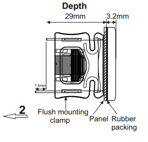
Depth
Flush mounting clamp
Panel
Rubber packing
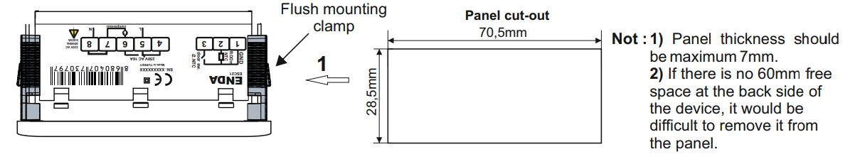
Panel cut-out
Note
Panel thickness should be a maximum of 7 mm.
If there is no 60 mm free space on the back side of the device, it would be difficult to remove it from the panel. - If there is not 60 mm of free space at the back of the device, it will be difficult to remove it from the panel.
Description of LEDs and buttons

| LED |
Description |
 |
ON/OFF
- If the LED is on, the device is Off |
 |
Compressor
- If the LED is on, the compressor is on
- If the LED is flashing, compressor protection is in progress |
 |
Defrost
- If the LED is on, defrosting is in progress
- If the LED is flashing, condensation is in progress |
 |
Celcius
- if the LED is lit, the temperature is displayed in Celsius. |
 |
Fahrenheit
- if the LED is lit, the temperature is displayed in Fahrenheit. |
 |
Power Saving
- If the LED is lit, the power saving function is enabled. |
 |
Warning
- If the LED is flashing, the alarm and fault functions are in progress. |
| Button |
Description |
 |
- In "Operating Mode", shows the value
- in "Programming Mode", displays the value of the selected parameter and confirms the changed value. |
 |
- in "Operation Mode", manual defrosting, if conditions allow.
- in "Programming Mode", switching between parameters and increasing the value of the selected parameter. |
 |
- in "Operation Mode", displays the evaporator temperature (P4=1).
- in "Programming Mode", Programming", switching between parameters and decreasing the value of the selected parameter |
 |
- in "Operating Mode", turning the device off/on
- in "Programming Mode", returning to Operating Mode |
1. Viewing and changing the setpoint

Translation: Measured Value -> Measured Value
If the button is pressed for 2 seconds in "Operation Mode," the setpoint value is displayed for 3 seconds. During this time, you can change the setpoint value using the  buttons.
2. Reading the value measured by the defrost probe
Translation: Measured Value -> Measured Value
In "Operation Mode", if the second input type is set to Analog Input (P4=1), pressing the  button for 5 seconds will display the value measured by the defrost probe.
3. Locking and unlocking buttons

Translation: Measured Value -> Measured Value
Keys are locked. -> The buttons are locked.
If the  buttons are pressed simultaneously for 3 seconds or no buttons are pressed for 1 minute in "Operation Mode", the message Lc will be displayed and the buttons will be locked. If the buttons are locked and any button is pressed for 2 seconds in "Operation Mode", the message uL will be displayed and the buttons will be unlocked.
4. Manual Defrosting
If the  button is pressed for 4 seconds in "Operation Mode", the defrosting process is manually enabled or disabled.
1) If parameter d3=0, manual defrosting is also disabled.
2) If the second input type is set to Analog Input (P4=1), defrosting will not start if the measured value of the defrost probe is greater than the value of parameter d2.
5. Manually turning the device on/off
If the button is pressed for 3 seconds in "Operating Mode" (without button lock), the display turns off, temperature measurement and control are not performed, and the output becomes passive. If the button is pressed again for 3 seconds, the display turns on, and the device continues to measure and control the temperature.
6. Factory Settings
If the PS parameter is set to 1: The PA Safety Parameter is set to -44 and the button is pressed, the dF message will appear on the display. If the button is pressed again while the dF message is displayed, the "---" message will flash for 4 seconds, then the device will revert to the factory settings and return to "Operation Mode".
If the PS parameter is set to 0: if the button is pressed first, and then the button is pressed and held together for 5 seconds in "Operation Mode", the dF message will appear on the display, the device will return to the factory settings and return to "Operation Mode". will revert to factory settings and return to "Operation Mode."
7. Displayed update dates

Translation: Measured Value -> Measured Value
YY/MM/DD -> YY/MM/DD
If the buttons are pressed simultaneously in "Running Mode", the update date will be displayed in the YY/MM/DD format.
8. Changing Parameter Values

Translation: RUNNING MODE -> OPERATION MODE
Temperature Value -> Temperature Value
Press the SET key for 4 seconds to enter settings mode -> Press the SET key for 4 seconds to enter settings mode
Settings -> Settings
Password Activation Msg. -> Password Activation Message
If the value -23 is entered, the parameter settings are accessible -> If the value -23 is entered, the parameter settings will be accessible
Parameter settings -> Parameter Settings
If the button is pressed for 4 seconds in "Operating Mode", the password message (PA) is displayed on the screen. By pressing the button, set the password to "-23" using the buttons, then click again to enter the Parameter Settings. Thanks to the buttons, we can select a specific parameter, then by clicking , the parameter value will be displayed. The value of the appropriate parameter can be changed using the buttons. If no operation is performed while the parameter value is displayed or the button is pressed again, the parameter name will be returned. If the button is pressed while the parameter name is displayed, this time the exit will occur without waiting.
Fault/Alarm - definitions of displayed information
| Display |
Information |
 |
Cabin sensor failure
-check the sensor connection
-the compressor is operating according to the parameters C4 and C5 |
 |
Defrost probe failure
-check the sensor connection
-if P4=1, defrosting will not work |
 |
Low temperature alarm
-check parameters A0, A1, A2 |
 |
High temperature alarm
-check parameters A0, A4, A5 |
 |
Door alarm
-check digital input
-check parameters i0, i1, i2 |
 |
Multifunction digital input alarm
-check digital input
-check i0, i1 parameters |
 |
Key lock message
-to change key lock settings, see: Locking and unlocking buttons |
 |
Key unlock message
-to change key lock settings, see: Locking and unlocking buttons buttons |
 |
Factory reset message
The device starts operating according to the factory settings |
 |
Defrost message
-defrosting in progress
-check parameter d6 |
Detailed information about the parameters can be found in the catalog card.


