-
-
-
Category
-
Semiconductors
- Diodes
- Thyristors
-
Electro-insulated Modules
- Electro-insulated Modules | VISHAY (IR)
- Electro-insulated Modules | INFINEON (EUPEC)
- Electro-insulated Modules | Semikron
- Electro-insulated Modules | POWEREX
- Electro-insulated Modules | IXYS
- Electro-insulated Modules | POSEICO
- Electro-insulated Modules | ABB
- Electro-insulated Modules | TECHSEM
- Go to the subcategory
- Bridge Rectifiers
-
Transistors
- Transistors | GeneSiC
- SiC MOSFET Modules | Mitsubishi
- SiC MOSFET Modules | STARPOWER
- Module SiC MOSFET ABB’s
- IGBT Modules | MITSUBISHI
- Transistor Modules | MITSUBISHI
- MOSFET Modules | MITSUBISHI
- Transistor Modules | ABB
- IGBT Modules | POWEREX
- IGBT Modules | INFINEON (EUPEC)
- Silicon Carbide (SiC) semiconductor elements
- Go to the subcategory
- Gate Drivers
- Power Blocks
- Go to the subcategory
- Electrical Transducers
-
Passive components (capacitors, resistors, fuses, filters)
- Resistors
-
Fuses
- Miniature Fuses for electronic circuits - ABC & AGC Series
- Tubular Fast-acting Fuses
- Time-delay Fuse Links with GL/GG & AM characteristics
- Ultrafast Fuse Links
- Fast-acting Fuses (British & American standard)
- Fast-acting Fuses (European standard)
- Traction Fuses
- High-voltage Fuse Links
- Go to the subcategory
- Capacitors
- EMI Filters
- Supercapacitors
- Power surge protection
- TEMPEST emission revealing filters
- Surge arrester
- Go to the subcategory
-
Relays and Contactors
- Relays and Contactors - Theory
- 3-Phase AC Semiconductor Relays
- DC Semiconductor Relays
- Controllers, Control Systems and Accessories
- Soft Starters and Reversible Relays
- Electromechanical Relays
- Contactors
- Rotary Switches
-
Single-Phase AC Semiconductor Relays
- AC ONE PHASE RELAYS 1 series| D2425 | D2450
- One phase semiconductor AC relays CWA and CWD series
- One phase semiconductor AC relays CMRA and CMRD series
- One phase semiconductor AC relays - PS series
- Double and quadruple semiconductor AC relays - D24 D, TD24 Q, H12D48 D series
- One phase semiconductor relays - gn series
- Ckr series single phase solid state relays
- One phase AC semiconductor relays for DIN bus - ERDA I ERAA series
- 150A AC single phase relays
- Rail Mountable Solid State Relays With Integrated Heat Sink - ENDA, ERDA1 / ERAA1 series
- Go to the subcategory
- Single-Phase AC Semiconductor Relays for PCBs
- Interface Relays
- Go to the subcategory
- Cores and Other Inductive Components
- Heatsinks, Varistors, Thermal Protection
- Fans
- Air Conditioning, Accessories for Electrical Cabinets, Coolers
-
Batteries, Chargers, Buffer Power Supplies and Inverters
- Batteries, Chargers - Theoretical Description
- Modular Li-ion Battery Building Blocks, Custom Batteries, BMS
- Batteries
- Battery Chargers and Accessories
- Uninterruptible Power Supply and Buffer Power Supplies
- Inverters and Photovoltaic Equipments
- Energy storage
- Fuel cells
- Lithium-ion batteries
- Go to the subcategory
-
Automatics
- Spiralift Lifts
- Futaba Drone Parts
- Limit Switches, Microswitches
- Sensors, Transducers
-
Infrared Thermometers (Pyrometers)
- IR-TE Series - Water-proof Palm-sized Radiation Thermometer
- IR-TA Series - Handheld Type Radiation Thermometer
- IR-H Series - Handheld Type Radiation Thermometer
- IR-BA Series - High-speed Compact Radiation Thermometer
- IR-FA Series - Fiber Optic Radiation Thermometer
- IR-BZ Series - Compact Infrared Thermometers
- Go to the subcategory
- Counters, Time Relays, Panel Meters
- Industrial Protection Devices
- Light and Sound Signalling
- Thermographic Camera
- LED Displays
- Control Equipments
- Go to the subcategory
-
Cables, Litz wires, Conduits, Flexible connections
- Wires
- Cable feedthroughs and couplers
- Litz wires
-
Cables for extreme applications
- Extension and Compensation cables
- Thermocouple cables
- Connection cables for PT sensors
- Multi-conductor wires (temp. -60C to +1400C)
- Medium voltage cables
- Ignition wires
- Heating cables
- Single conductor cables (temp. -60C to +450C)
- Railway cables
- Heating cables Ex
- Cables for the defense industry
- Go to the subcategory
- Sleevings
-
Braids
- Flat Braids
- Round Braids
- Very Flexible Flat Braids
- Very Flexible Round Braids
- Cylindrical Cooper Braids
- Cylindrical Cooper Braids and Sleevings
- Flexible Earthing Connections
- PCV Insulated Copper Braids (temp. up to 85C)
- Flat Aluminium Braids
- Junction Set - Braids and Tubes
- Steel Braids
- Go to the subcategory
- Traction Equipment
- Cable Terminals
- Flexible Insulated Busbars
- Flexible Multilayer Busbars
- Cable Duct Systems
- Go to the subcategory
- View all categories
-
Semiconductors
-
-


What are the methods for controlling conducted emissions?

In recent years, we have witnessed a rapid development of the electric vehicle (EV) market, and consequently — the infrastructure for their charging. The number of electric cars is growing quickly — in the UK alone, there are over 32.5 million registered vehicles, with an increasing share being electric or plug-in hybrid vehicles. This creates a huge demand for efficient, safe, and standards-compliant EV chargers.
For many companies, especially startups, entering this market means enormous growth potential. However, developing such equipment entails significant challenges — particularly in the area of electromagnetic compatibility (EMC), specifically conducted emissions.
Why is conducted emission a problem?
Conducted emission is a form of electromagnetic interference that can enter the power supply network through cables — most often via the neutral or grounding conductor. In the case of EV chargers, which usually contain high-efficiency DC/DC converters, the risk of generating such disturbances is very high. The alternating current generated by the charger, if not properly suppressed, can lead to exceeding the limits allowed by EMC standards.
This is not just a technical issue — non-compliance with standards may prevent obtaining necessary certifications (such as CE, FCC, UKCA), and thus block the product’s market launch.
Impact on EMC compliance and the EV market
From our experience, many young companies underestimate the role of electromagnetic compatibility at the early stages of the project. They often come to us only when their device fails EMC tests, and the costs of delays and redesigns start to increase exponentially.
For this reason, conducted emission is one of the topics that must be understood and controlled from the very beginning of the design work. This issue combines elements of electronics, mechanics, software, as well as knowledge about interference currents and return current paths. Effective management of conducted emission not only avoids formal problems but also improves the overall reliability and safety of the device.
Main sources of conducted emission in EV chargers
The role of the DC/DC converter
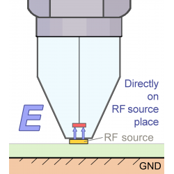
At the heart of most modern EV chargers is a high-efficiency DC/DC converter whose task is to convert the voltage to the appropriate battery charging voltage. Thanks to pulse processing, such a system achieves high efficiency but simultaneously generates strong disturbances at frequencies of tens of kHz or more. Some of these disturbances penetrate into the neutral or protective conductor (PE), creating uncontrolled conducted emission. Without proper filtering and electromagnetic wave separation, the DC/DC converter can become the main source of interference that returns to the customer’s installation and other devices in the power network.
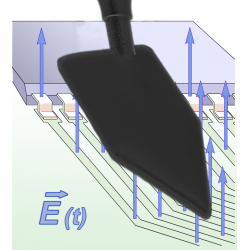
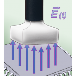
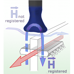
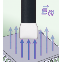
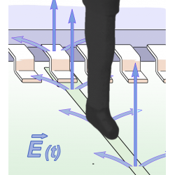
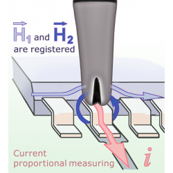
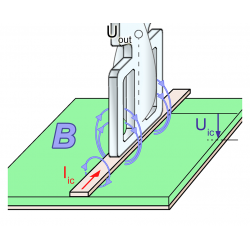
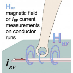
Return path of the signal and grounding
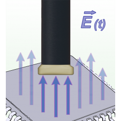
Conducted emission always follows the shortest return path to the source of interference. In EV chargers, this signal usually returns via the neutral or protective conductor, and in some designs also through enclosure or shielding elements. A key role is played by decoupling capacitors — “Y capacitors” between the primary and secondary sides of the power circuit, and “X capacitors” mounted between the phase and neutral conductors. Their selected values affect the noise attenuation level but simultaneously must not exceed the limits specified by standards (e.g., Y ≤ 4.7 nF) to avoid compromising insulation safety. Understanding the actual return path — along with precise measurement of grounding and conductor impedance — is essential to effectively eliminate conducted emission and ensure stable charger operation.
Good approach to solving EMC problems
Preliminary tests in an EMC laboratory
Before starting modifications of the system, preliminary investigations should be performed in an EMC laboratory. One or two days are reserved there to measure the levels of conducted emissions and determine the disturbance characteristics in a controlled environment.
Simulations and analyses of return paths
Alongside practical tests, simulations of interference return paths are conducted. Based on the DC/DC converter model and filtering circuit, the impedance of individual elements and the distribution of disturbance currents between phase, neutral, and protective conductors are analyzed. This allows predicting which parts of the circuit contribute most to conducted emission. Our results are compared with industry publications (e.g., example simulations described in literature) and verified against real laboratory measurements. Such an iterative method — test → simulation → correction → test — enables achieving very high confidence (even 99%) in the effectiveness of introduced corrections.
Practical methods of reducing conducted emission
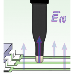
Increasing the impedance of the DC/DC converter
An important step was introducing a small additional impedance in the return path between the converter’s ground and earth. Thanks to this, part of the disturbance current at around 1 kHz frequency is “closed” in the circuit instead of leaking into the power network. This correction — although it somewhat lowers the overall system efficiency — allows significantly reducing conducted emission without risking exceeding the permissible attenuation level.
Optimization of capacitor values
Due to the limitation of Y capacitors to a maximum of 4.7 nF and X capacitors to safe values, iterative tests can be conducted to select the most effective capacitances just below the norm limits. This achieves the maximum possible noise attenuation while maintaining full insulation safety and minimal impact on converter operation.
Implementation and testing of solutions
The process of applying corrections
After approving the simulation model and preliminary lab tests, changes must be applied directly to the printed circuit board: components increasing impedance, changed capacitor values, and optimized ground paths. Every modification must be documented and immediately retested under EMC test conditions to verify the effects of the correction.
Final tests and CE/FCC/UKCA certifications
After passing preliminary lab measurements, time must be booked at an EMC facility that will carry out the full set of certification tests. Using the same facility for all tests shortens the homologation time and avoids unnecessary repetitions. After obtaining CE, FCC, and UKCA marks, the client can promptly launch the product on the market.
Summary and recommendations
1. Thorough analysis of emission sources
Identify the main interference generation points (e.g., DC/DC converter and return path) before making changes.
2. Preliminary tests in an EMC laboratory
Regular tests in one trusted facility provide repeatable results and facilitate verification of the effectiveness of every correction.
3. Iterative simulations and measurements
Combine computer analyses with practical lab measurements — this shortens diagnostics time and allows achieving over 99% confidence in solution effectiveness.
4. Optimization of filters (X/Y capacitors)
Select values just below norm limits (e.g., Y ≤ 4.7 nF) to maximize noise attenuation while ensuring insulation safety.
5. Increasing the return path impedance
Introduce a small additional impedance between converter ground and earth to limit disturbance currents entering the network.
6. Final tests in a certified laboratory
Use the same accredited facility at all homologation stages (CE/FCC/UKCA) to avoid inconsistencies and delays.
7. Close cooperation with EMC experts
Build long-term relationships with engineers and laboratories to implement corrections faster and optimize the design.
By applying these principles, any startup or EV charger manufacturer can significantly shorten homologation time, reduce correction costs, and bring a finished product to market faster. Cooperation with experienced EMC engineers and reliable laboratories is the key to success in the dynamic electric vehicle industry.
Related products
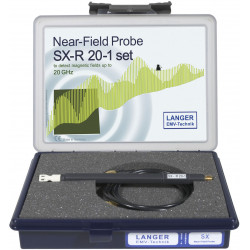
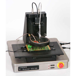


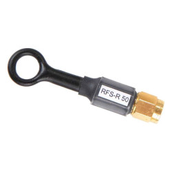
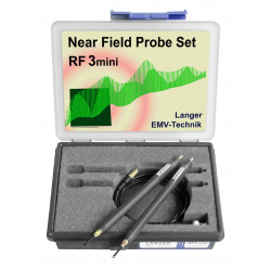
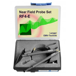
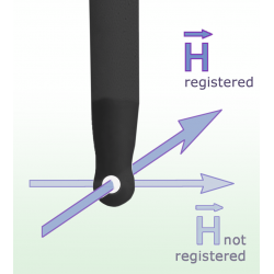
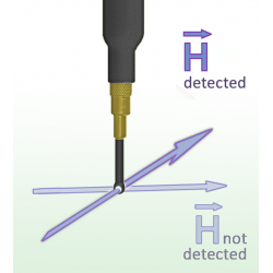
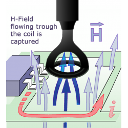
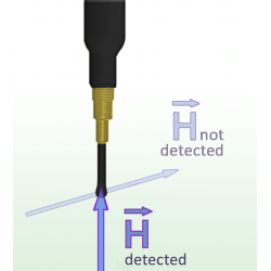
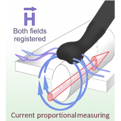
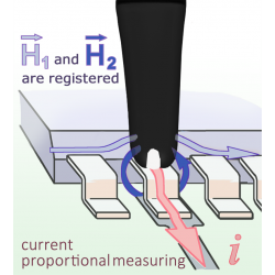
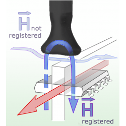
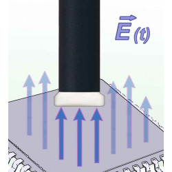
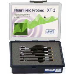
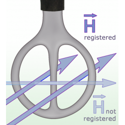
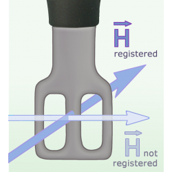
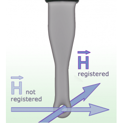
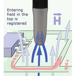
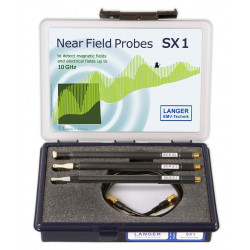
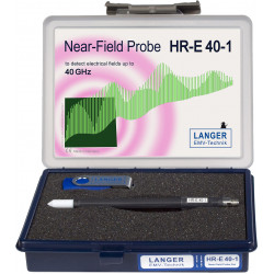
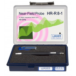
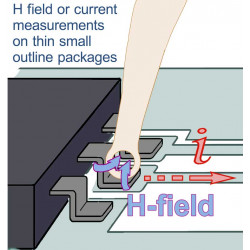
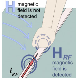
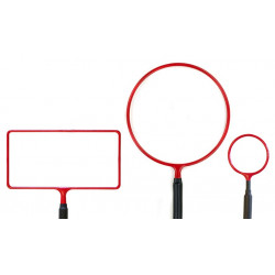
Scanner Probes 30 MHz up to 3 GHz
Price: 0.00 PLN
The RFS set consits of three passive near field probes designed for the use...


Related posts
Now available – DC/DC converters from PREMIUM
We introduced a novelty to our permanent offer in DACPOL in the category of power supplies and converters and today...
Read more
New release in DACPOL lighting for lathes – Kira covers
We introduce a new product into the DACPOL category of industrial lighting and today we offer KIRA covers for...
Read more
Leave a comment