-
-
-
Category
-
Semiconductors
- Diodes
- Thyristors
-
Electro-insulated Modules
- Electro-insulated Modules | VISHAY (IR)
- Electro-insulated Modules | INFINEON (EUPEC)
- Electro-insulated Modules | Semikron
- Electro-insulated Modules | POWEREX
- Electro-insulated Modules | IXYS
- Electro-insulated Modules | POSEICO
- Electro-insulated Modules | ABB
- Electro-insulated Modules | TECHSEM
- Go to the subcategory
- Bridge Rectifiers
-
Transistors
- Transistors | GeneSiC
- SiC MOSFET Modules | Mitsubishi
- SiC MOSFET Modules | STARPOWER
- Module SiC MOSFET ABB’s
- IGBT Modules | MITSUBISHI
- Transistor Modules | MITSUBISHI
- MOSFET Modules | MITSUBISHI
- Transistor Modules | ABB
- IGBT Modules | POWEREX
- IGBT Modules | INFINEON (EUPEC)
- Silicon Carbide (SiC) semiconductor elements
- Go to the subcategory
- Gate Drivers
- Power Blocks
- Go to the subcategory
- Electrical Transducers
-
Passive components (capacitors, resistors, fuses, filters)
- Resistors
-
Fuses
- Miniature Fuses for electronic circuits - ABC & AGC Series
- Tubular Fast-acting Fuses
- Time-delay Fuse Links with GL/GG & AM characteristics
- Ultrafast Fuse Links
- Fast-acting Fuses (British & American standard)
- Fast-acting Fuses (European standard)
- Traction Fuses
- High-voltage Fuse Links
- Go to the subcategory
- Capacitors
- EMI Filters
- Supercapacitors
- Power surge protection
- TEMPEST emission revealing filters
- Surge arrester
- Go to the subcategory
-
Relays and Contactors
- Relays and Contactors - Theory
- 3-Phase AC Semiconductor Relays
- DC Semiconductor Relays
- Controllers, Control Systems and Accessories
- Soft Starters and Reversible Relays
- Electromechanical Relays
- Contactors
- Rotary Switches
-
Single-Phase AC Semiconductor Relays
- AC ONE PHASE RELAYS 1 series| D2425 | D2450
- One phase semiconductor AC relays CWA and CWD series
- One phase semiconductor AC relays CMRA and CMRD series
- One phase semiconductor AC relays - PS series
- Double and quadruple semiconductor AC relays - D24 D, TD24 Q, H12D48 D series
- One phase semiconductor relays - gn series
- Ckr series single phase solid state relays
- One phase AC semiconductor relays for DIN bus - ERDA I ERAA series
- 150A AC single phase relays
- Rail Mountable Solid State Relays With Integrated Heat Sink - ENDA, ERDA1 / ERAA1 series
- Go to the subcategory
- Single-Phase AC Semiconductor Relays for PCBs
- Interface Relays
- Go to the subcategory
- Cores and Other Inductive Components
- Heatsinks, Varistors, Thermal Protection
- Fans
- Air Conditioning, Accessories for Electrical Cabinets, Coolers
-
Batteries, Chargers, Buffer Power Supplies and Inverters
- Batteries, Chargers - Theoretical Description
- Modular Li-ion Battery Building Blocks, Custom Batteries, BMS
- Batteries
- Battery Chargers and Accessories
- Uninterruptible Power Supply and Buffer Power Supplies
- Inverters and Photovoltaic Equipments
- Energy storage
- Fuel cells
- Lithium-ion batteries
- Go to the subcategory
-
Automatics
- Spiralift Lifts
- Futaba Drone Parts
- Limit Switches, Microswitches
- Sensors, Transducers
-
Infrared Thermometers (Pyrometers)
- IR-TE Series - Water-proof Palm-sized Radiation Thermometer
- IR-TA Series - Handheld Type Radiation Thermometer
- IR-H Series - Handheld Type Radiation Thermometer
- IR-BA Series - High-speed Compact Radiation Thermometer
- IR-FA Series - Fiber Optic Radiation Thermometer
- IR-BZ Series - Compact Infrared Thermometers
- Go to the subcategory
- Counters, Time Relays, Panel Meters
- Industrial Protection Devices
- Light and Sound Signalling
- Thermographic Camera
- LED Displays
- Control Equipments
- Go to the subcategory
-
Cables, Litz wires, Conduits, Flexible connections
- Wires
- Cable feedthroughs and couplers
- Litz wires
-
Cables for extreme applications
- Extension and Compensation cables
- Thermocouple cables
- Connection cables for PT sensors
- Multi-conductor wires (temp. -60C to +1400C)
- Medium voltage cables
- Ignition wires
- Heating cables
- Single conductor cables (temp. -60C to +450C)
- Railway cables
- Heating cables Ex
- Cables for the defense industry
- Go to the subcategory
- Sleevings
-
Braids
- Flat Braids
- Round Braids
- Very Flexible Flat Braids
- Very Flexible Round Braids
- Cylindrical Cooper Braids
- Cylindrical Cooper Braids and Sleevings
- Flexible Earthing Connections
- PCV Insulated Copper Braids (temp. up to 85C)
- Flat Aluminium Braids
- Junction Set - Braids and Tubes
- Steel Braids
- Go to the subcategory
- Traction Equipment
- Cable Terminals
- Flexible Insulated Busbars
- Flexible Multilayer Busbars
- Cable Duct Systems
- Go to the subcategory
- View all categories
-
Semiconductors
-
-


Transformers for thyristor control – what are they and what are they used for?

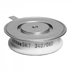
A thyristor is one of the most important power semiconductor components used in electronic circuits. It consists of four layers of semiconductor material and has three terminals: an anode, a cathode, and a gate. When a suitable voltage appears between the anode and cathode and a current pulse is applied to the gate, the thyristor switches to the conducting state and begins to conduct current in the forward direction. It is the gate current that controls its turn-on.
The thyristor conducts until the current in the circuit drops below a certain holding value or a special thyristor turn-off method is applied. For this reason, it is often compared to a switch that can be turned on but is not always easy to turn off.
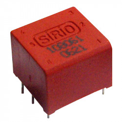
Transformer in thyristor circuits
The transformer in thyristor control circuits plays an isolating and matching role. It allows the control circuits to be safely connected to the thyristor while ensuring the transmission of the pulses needed to turn on the thyristor. The secondary windings of the transformer allow gate pulses to be transmitted relative to the cathode, maintaining proper current and voltage values.
The use of a transformer also protects the controller and the entire control section from interference and high voltage present in power circuits. This allows thyristors used in high-power devices to be controlled by small signals from low-voltage electronic circuits.
Transistor vs. thyristor – differences
Although thyristors and transistors are semiconductor devices, their operating principles differ significantly. A bipolar transistor or MOSFET operates linearly and can control current flow continuously depending on the control signal. A thyristor, on the other hand, after a gate pulse is applied, switches to the conducting state and remains there until the current in the circuit drops.
One can say that a transistor resembles an adjustable valve, while a thyristor is like an ignition switch. In many industrial applications, circuits are used where both elements cooperate to implement power control.
Triac – a variation of the thyristor
A triac is a semiconductor device similar to a thyristor but capable of conducting current in both directions. This makes triacs widely used in mains-powered devices where alternating current flows. A gate pulse can turn on the triac regardless of the polarity of the sinusoid.
Triacs are used in AC power control of loads, such as dimmers, speed controllers, or phase control circuits. In such systems, pulse transformers are often used to enable proper connection and isolation.
Electronic phase control circuit
Phase control is one of the most common methods of using thyristors and triacs. It involves turning on the thyristor only at a specific portion of the AC voltage sine wave. In this way, the power delivered to the load can be regulated by controlling the current flow.
The transformer used in phase control delivers the gate pulse at the appropriate moment, corresponding to the phase angle of the mains voltage. This allows smooth power regulation in AC-powered devices.
Operation principle of thyristor and control transformer
The thyristor operates based on positive feedback between internal structures, which causes the device to conduct current after a gate pulse is applied. The transformer's task is to deliver this pulse safely and in a controlled manner.
The schematic of such a system includes a power supply voltage source, a thyristor with anode and cathode, and a transformer with secondary windings. The pulse passing through the gate area triggers the thyristor. Current and voltage values must be selected according to the specifications to avoid damaging the thyristor.
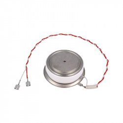
GTO thyristor – turn-off thyristor
An interesting variation is the GTO (Gate Turn-Off) thyristor, which can not only be turned on but also turned off using a gate pulse. In this case, the control transformer must be able to transmit both positive and negative gate current pulses. This allows the GTO thyristor to be used in more advanced power control systems and DC motor drives.
Thyristor characteristics and symbol
The thyristor symbol shows the anode, cathode, and gate. The current-voltage characteristic indicates that the thyristor does not conduct current in the reverse direction, while in the forward direction it switches to the conducting state after a gate pulse is applied. Resistance values in the conducting state are very low, allowing control of high power.
Practical applications
Thyristors are used in power control circuits, controlled rectifiers, DC motor drives, as well as in everyday electronic devices. The transformer in such circuits provides galvanic isolation and signal matching for control signals.
Phase control using thyristors and triacs allows smooth regulation of voltage and current in many devices. This enables dimming of lamps, motor speed control, and power adjustment of heaters.
Schematics and electronic circuits
Thyristor circuit schematics usually include elements such as a protective diode, gate current limiting resistor, and pulse transformer. Such a circuit can be connected to a mains system, keeping the correct polarity in mind.
The operation of a thyristor can be tested under simple conditions by checking the current flow between the anode and cathode after applying a gate signal. If the thyristor conducts current, it means the trigger pulse has been correctly delivered.
Summary
The thyristor is a semiconductor device of great importance in power electronics. A transformer for thyristor control is a key element that enables safe and effective connection of control circuits. Thanks to it, phase control, current flow regulation, and power adjustment can be implemented in many industrial and domestic applications.
We invite you to explore our offer and take advantage of solutions that fit your needs. Contact us to discover more possibilities in the field of power electronics.
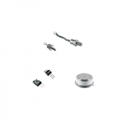
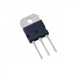
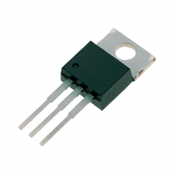
Related products
Related posts
Thermally conductive materials in power storages
Technological development caused a need in electric engineering to search for new solutions in heat conduction.
Read more
Measuring power and energy in electric circuits
Power meters and network parameter analyzers are intended for identifying anomalies of power supply in single-phase...
Read more
Wentylatory przemysłowe - rodzaje, właściwości
W zależności od obiektu, charakteru stanowisk pracowniczych, oraz szeregu indywidualnych czynników otoczenia w...
Read more
Leave a comment