CWT Mini and CWT MiniHF series

Photos are for informational purposes only. View product specification

please use latin characters

Manufacturer: PEM

CWT Mini series

The CWT mini series is designed for measuring AC currents over a wide measurement range and a large frequency bandwidth. The MINI version has a small coil cross-section and a small diameter, making it ideal for measuring current in hard-to-reach areas of an electrical circuit. The voltage output via a BNC connector allows direct connection to an oscilloscope or other recording device.

Key Features

Enhanced low frequency performance
Extended low frequency characteristic.
Rated currents
Rated currents from 60 A to 300 kA (peak values).

Wide bandwidth
Models cover the range from 0.1 Hz to 16 MHz.

Thin coils and high insulation
Thin coils with a cross-section diameter of 3.5 mm for 2 kV insulation and 4.5 mm for 5 kV insulation (peak value).
Cable length selection
Longer cables than the standard 1 m, 2.5 m, and 4 m are available – on request.
Custom coil length
Coils longer than the standard 100 mm and 200 mm are available on request.


Applications

  • Measurements of 50/60 Hz mains frequency and higher harmonics
  • Pulse currents and pulse power measurements with long pulse durations.
  • Measurement of small AC currents in the presence of large DC currents (e.g., capacitor ripple monitoring).
  • Measurement of currents in hard-to-access conductors, such as densely arranged busbars.
  • Monitoring power quality in variable speed drives, UPS power supplies, energy systems, or SMPS circuits.


Meets standards

  • CE
  • EMC EN 61326-1 2006
  • IEC 61010-1
  • IEC 61010-2-032


Technical Parameters

Output
  • ±6V for peak current max. for R>100kΩ (recommended oscilloscope input R=1MΩ)
  • ±2 V (peak value), sensitivity is half of the nominal value at 50 Ω load.
Accuracy
  • Calibrated to ±0.2% of reading when conductor is centered in the Rogowski coil loop.
  • Conductor position in the coil (for 2 mm diameter conductor) – typically ±2% of reading.
  • Conductor position in the coil (for 10 mm diameter conductor) – typically ±1% of reading.
Linearity to current amplitude ±0.05% of reading
DC Offset Maximum ±3mV for T=25°C
Temperature Coil and cable: -20…100°C, integrator: 0…40°C
Coil Voltage
  • 2 kV (peak value) – 3.5 mm thick coil.
  • 5 kV (peak value) – 4.5 mm thick coil.
Coil Circumference 100, 200 mm – larger sizes possible on request
Power Supply B - standard: 4 x AA 1.5V alkaline batteries, typical operating time 25h R – rechargeable: 4x AA 1.2 NiMH batteries, typical lifespan 10h, external charging possible
Output BNC


Model Sensitivity
(mV/A)
Max Current
(A)
Max Noise
(mVp-p)
Droop*
(%/ms)
LF Bandwidth
(-3dB)(Hz)
Max di/dt
(kA/μs)
Bandwidth (-3dB)
(MHz)
100 mm 200 mm
CWTMini/03 100 60 15 6.6 7.0 1.0 10 5
CWTMini/06 50 120 15 4.8 5.0 2.0 10 5
CWTMini/1 20 300 12 3.6 4.0 2.5 20 15
CWTMini/3 10 600 10 1.8 2.0 5.0 20 15
CWTMini/6 5.0 1200 10 0.8 0.9 25 20 15
CWTMini/15 2.0 3000 8.0 0.4 0.5 25 20 15
CWTMini/30 1.0 6000 7.0 0.25 0.3 40 20 15
CWTMini/60 0.5 12000 5.0 0.2 0.2 40 20 15
CWTMini/150 0.2 30000 5.0 0.1 0.1 40 20 15
CWTMini/300 0.1 60000 5.0 0.05 0.05 40 20 15
CWTMini/600 0.05 120000 5.0 0.03 0.02 40 20 15
CWTMini/1500 0.02 300000 5.0 0.03 0.02 40 20 15

* - Percentage drop of the output signal with a square wave

Send an inquiry

Are you interested in this product? Do you need additional information or individual pricing?
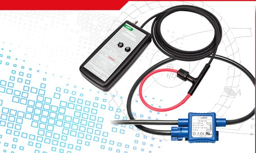
Contact us
ASK FOR THE PRODUCT close
Thank you for sending your message. We will respond as soon as possible.
ASK FOR THE PRODUCT close
Browse

Add to Wishlist

You must be logged in

The CWT mini series is designed for measuring AC currents over a wide measurement range and a large frequency bandwidth. The MINI version has a small coil cross-section and a small diameter, making it ideal for measuring current in hard-to-reach areas of an electrical circuit. The voltage output via a BNC connector allows direct connection to an oscilloscope or other recording device.

Key Features

Enhanced low frequency performance
Extended low frequency characteristic.
Rated currents
Rated currents from 60 A to 300 kA (peak values).

Wide bandwidth
Models cover the range from 0.1 Hz to 16 MHz.

Thin coils and high insulation
Thin coils with a cross-section diameter of 3.5 mm for 2 kV insulation and 4.5 mm for 5 kV insulation (peak value).
Cable length selection
Longer cables than the standard 1 m, 2.5 m, and 4 m are available – on request.
Custom coil length
Coils longer than the standard 100 mm and 200 mm are available on request.


Applications

  • Measurements of 50/60 Hz mains frequency and higher harmonics
  • Pulse currents and pulse power measurements with long pulse durations.
  • Measurement of small AC currents in the presence of large DC currents (e.g., capacitor ripple monitoring).
  • Measurement of currents in hard-to-access conductors, such as densely arranged busbars.
  • Monitoring power quality in variable speed drives, UPS power supplies, energy systems, or SMPS circuits.


Meets standards

  • CE
  • EMC EN 61326-1 2006
  • IEC 61010-1
  • IEC 61010-2-032


Technical Parameters

Output
  • ±6V for peak current max. for R>100kΩ (recommended oscilloscope input R=1MΩ)
  • ±2 V (peak value), sensitivity is half of the nominal value at 50 Ω load.
Accuracy
  • Calibrated to ±0.2% of reading when conductor is centered in the Rogowski coil loop.
  • Conductor position in the coil (for 2 mm diameter conductor) – typically ±2% of reading.
  • Conductor position in the coil (for 10 mm diameter conductor) – typically ±1% of reading.
Linearity to current amplitude ±0.05% of reading
DC Offset Maximum ±3mV for T=25°C
Temperature Coil and cable: -20…100°C, integrator: 0…40°C
Coil Voltage
  • 2 kV (peak value) – 3.5 mm thick coil.
  • 5 kV (peak value) – 4.5 mm thick coil.
Coil Circumference 100, 200 mm – larger sizes possible on request
Power Supply B - standard: 4 x AA 1.5V alkaline batteries, typical operating time 25h R – rechargeable: 4x AA 1.2 NiMH batteries, typical lifespan 10h, external charging possible
Output BNC


Model Sensitivity
(mV/A)
Max Current
(A)
Max Noise
(mVp-p)
Droop*
(%/ms)
LF Bandwidth
(-3dB)(Hz)
Max di/dt
(kA/μs)
Bandwidth (-3dB)
(MHz)
100 mm 200 mm
CWTMini/03 100 60 15 6.6 7.0 1.0 10 5
CWTMini/06 50 120 15 4.8 5.0 2.0 10 5
CWTMini/1 20 300 12 3.6 4.0 2.5 20 15
CWTMini/3 10 600 10 1.8 2.0 5.0 20 15
CWTMini/6 5.0 1200 10 0.8 0.9 25 20 15
CWTMini/15 2.0 3000 8.0 0.4 0.5 25 20 15
CWTMini/30 1.0 6000 7.0 0.25 0.3 40 20 15
CWTMini/60 0.5 12000 5.0 0.2 0.2 40 20 15
CWTMini/150 0.2 30000 5.0 0.1 0.1 40 20 15
CWTMini/300 0.1 60000 5.0 0.05 0.05 40 20 15
CWTMini/600 0.05 120000 5.0 0.03 0.02 40 20 15
CWTMini/1500 0.02 300000 5.0 0.03 0.02 40 20 15

* - Percentage drop of the output signal with a square wave

Comments (0)