
Category


Photos are for informational purposes only. View product specification
please use latin characters
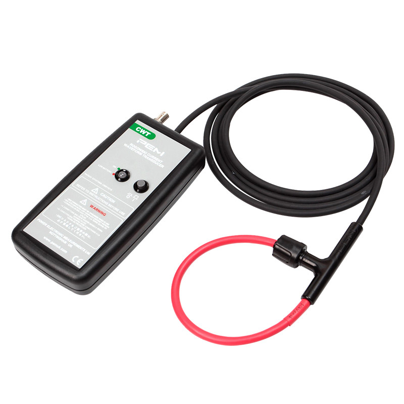
The CWT series is designed for measuring AC currents ranging from a few hundred milliamperes to several hundred kiloamperes and frequencies from tenths of a Hz to several tens of MHz. Typical applications for CWT Rogowski coils include measuring and recording the waveform of semiconductor switch currents, higher frequency sinusoidal signals, pulsating signals, and others characterized by high variability.
| Maximum di/dt Ability to operate at maximum di/dt up to 40 kA/µs. |
Rated Currents Rated currents from 600 A to 60 kA (peak values). |
|||
|
|
Isolated Coil Coil insulation: 10 kV (peak value) Coil cross-section diameter: max. 8.5 mm |
|||
| Custom Cable LengthLonger cables than standard 1 m, 2.5 m, and 4 m are available – upon request. | Custom Coil Length Coils longer than standard 300 mm, 500 mm, 700 mm, and 1000 mm are available upon request. |
| Output | ±6V for max peak current for R>100kΩ (recommended oscilloscope input R=1MΩ) |
| Accuracy | Calibrated to ±0.2% of reading with conductor centered in Rogowski coil loop. Conductor position in coil (for 10 mm diameter conductor) – typically ±1% of reading. |
| Linearity | up to current amplitude ±0.05% of reading |
| DC Offset | Maximum ±3mV for T=25°C |
| Temperature | Coil and cable: -20…100°C, integrator: 0…40°C |
| Coil Voltage | 10kV peak value - safe peak voltage to ground determined based on 15kVrms, 50Hz, 60s test. |
| Coil Circumference | 500, 700, 1000mm – larger sizes possible upon request |
| Coil Cross-section | 8.5mm max. (14mm with silicone sheath for protection against mechanical damage) |
| Power Supply | B - standard: 4 x AA 1.5V alkaline batteries, typical operating time 25h R – rechargeable: 4x AA 1.2 NiMH batteries, typical lifespan 10h, external charging possible |
| Output | BNC |
| Model | Sensitivity (mV/A) | Max Current (A) | Maximum Noise (mVp-p) | Droop* (%/ms) | LF Bandwidth (-3dB)(Hz) | Max di/dt Current (kA/μs) | Bandwidth (-3dB) (MHz) | |||
|---|---|---|---|---|---|---|---|---|---|---|
| 300 mm | 500 mm | 700 mm | 1000 mm | |||||||
| CWT/3N | 10 | 600 | 14 | 0.9 | 1.0 | 2.0 | 10 | 6.5 | 5 | 3.5 |
| CWT/6 | 5.0 | 1200 | 12 | 0.9 | 1.0 | 8.0 | 16 | 12.5 | 10 | 8 |
| CWT/15 | 2.0 | 3000 | 7.0 | 0.7 | 0.8 | 20 | 16 | 12.5 | 10 | 8 |
| CWT/30 | 1.0 | 6000 | 3.5 | 0.5 | 0.6 | 40 | 16 | 12.5 | 10 | 8 |
| CWT/60 | 0.5 | 12000 | 3.0 | 0.35 | 0.4 | 40 | 16 | 12.5 | 10 | 8 |
| CWT/150 | 0.2 | 30000 | 3.0 | 0.2 | 0.2 | 40 | 16 | 12.5 | 10 | 8 |
| CWT/300 | 0.1 | 60000 | 3.0 | 0.1 | 0.1 | 40 | 16 | 12.5 | 10 | 8 |
* - Percentage drop in output signal for a square wave
Are you interested in this product? Do you need additional information or individual pricing?
The CWT series is designed for measuring AC currents ranging from a few hundred milliamperes to several hundred kiloamperes and frequencies from tenths of a Hz to several tens of MHz. Typical applications for CWT Rogowski coils include measuring and recording the waveform of semiconductor switch currents, higher frequency sinusoidal signals, pulsating signals, and others characterized by high variability.
| Maximum di/dt Ability to operate at maximum di/dt up to 40 kA/µs. |
Rated Currents Rated currents from 600 A to 60 kA (peak values). |
|||
|
|
Isolated Coil Coil insulation: 10 kV (peak value) Coil cross-section diameter: max. 8.5 mm |
|||
| Custom Cable LengthLonger cables than standard 1 m, 2.5 m, and 4 m are available – upon request. | Custom Coil Length Coils longer than standard 300 mm, 500 mm, 700 mm, and 1000 mm are available upon request. |
| Output | ±6V for max peak current for R>100kΩ (recommended oscilloscope input R=1MΩ) |
| Accuracy | Calibrated to ±0.2% of reading with conductor centered in Rogowski coil loop. Conductor position in coil (for 10 mm diameter conductor) – typically ±1% of reading. |
| Linearity | up to current amplitude ±0.05% of reading |
| DC Offset | Maximum ±3mV for T=25°C |
| Temperature | Coil and cable: -20…100°C, integrator: 0…40°C |
| Coil Voltage | 10kV peak value - safe peak voltage to ground determined based on 15kVrms, 50Hz, 60s test. |
| Coil Circumference | 500, 700, 1000mm – larger sizes possible upon request |
| Coil Cross-section | 8.5mm max. (14mm with silicone sheath for protection against mechanical damage) |
| Power Supply | B - standard: 4 x AA 1.5V alkaline batteries, typical operating time 25h R – rechargeable: 4x AA 1.2 NiMH batteries, typical lifespan 10h, external charging possible |
| Output | BNC |
| Model | Sensitivity (mV/A) | Max Current (A) | Maximum Noise (mVp-p) | Droop* (%/ms) | LF Bandwidth (-3dB)(Hz) | Max di/dt Current (kA/μs) | Bandwidth (-3dB) (MHz) | |||
|---|---|---|---|---|---|---|---|---|---|---|
| 300 mm | 500 mm | 700 mm | 1000 mm | |||||||
| CWT/3N | 10 | 600 | 14 | 0.9 | 1.0 | 2.0 | 10 | 6.5 | 5 | 3.5 |
| CWT/6 | 5.0 | 1200 | 12 | 0.9 | 1.0 | 8.0 | 16 | 12.5 | 10 | 8 |
| CWT/15 | 2.0 | 3000 | 7.0 | 0.7 | 0.8 | 20 | 16 | 12.5 | 10 | 8 |
| CWT/30 | 1.0 | 6000 | 3.5 | 0.5 | 0.6 | 40 | 16 | 12.5 | 10 | 8 |
| CWT/60 | 0.5 | 12000 | 3.0 | 0.35 | 0.4 | 40 | 16 | 12.5 | 10 | 8 |
| CWT/150 | 0.2 | 30000 | 3.0 | 0.2 | 0.2 | 40 | 16 | 12.5 | 10 | 8 |
| CWT/300 | 0.1 | 60000 | 3.0 | 0.1 | 0.1 | 40 | 16 | 12.5 | 10 | 8 |
* - Percentage drop in output signal for a square wave
 Rogowski Coils – Construction and Principle of Operation
Your review appreciation cannot be sent
Report comment
Report sent
Your report cannot be sent
Write your review
Review sent
Your review cannot be sent
